
(RADAR)
(RF-HEAD)
(ANTENNAS)
(PROCESSING)
(WEATHER)
(HOME)
Homemade FM weather radar at 10GHz
Matjaz Vidmar, S53MV
2. RF head
In order to avoid the requirement for a high peak-power transmitter the design of a FMCW weather radar operating in the 10GHz amateur-radio frequency band was attempted. When compared to 5.6GHz long-range weather radar, the use of 10.24GHz allows an 11dB stronger Rayleigh scattering from precipitations. The range of a radar installed in a flat land (not on a mountaintop) is limited to around 30km due to the curvature of the Earth considering the height of the clouds, therefore the increased attenuation of precipitations is not important yet.
The radar main components are shown on the following drawing. Like with any radar, its performance mainly depends on the antenna(s) used. Additionally, in order to limit unwanted crosstalk in a FMCW radar, two separate antennas are used for transmission and reception:
Both transmission and reception antennas are of the same type, use the same polarization and are always pointed in the same direction of the target measured. Since interesting targets may span across the whole sky, two independent axis rotations, usually azimuth and elevation are both required. A standard amateur-radio two-axis rotor KR5600 is used for both azimuth and elevation. Unfortunately the accuracy nor mechanical strength of the latter does not match the requirements of the 90cm (30 lambda at 10GHz) diameter antennas with a beamwidth of around 2.5 degrees.
All of the RF components of the radar are installed close to both antennas on the same KR5600 azimuth/elevation rotor. All of the RF cables are therefore kept short and rigid. UT-141 semirigid coaxial cable is used to connect both antennas. The only connections to the remote indoor signal processing are the FM-radar beat signal at 0.2-48kHz and the +24V DC supply voltage. An internal +5V DC regulator supplies most circuits of the RF head. The power dissipation of the latter is useful to keep condensation moisture out of the RF head:

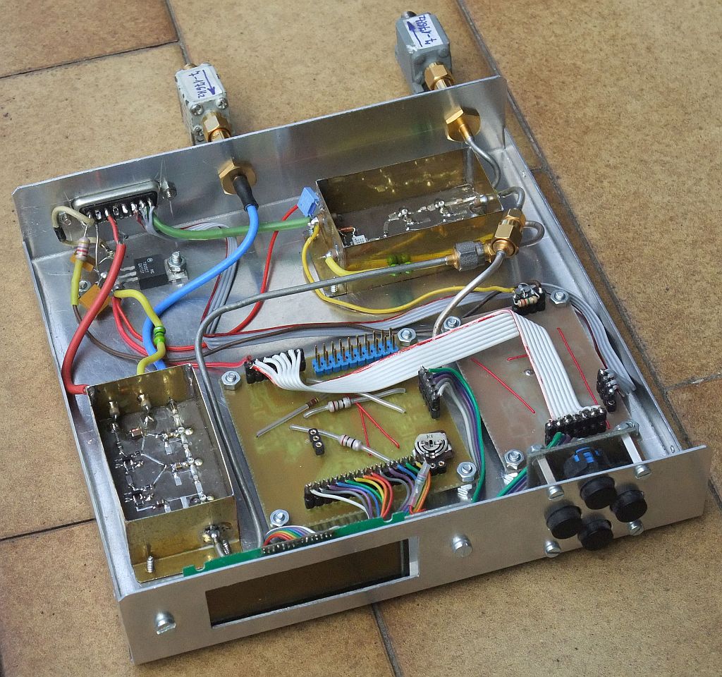
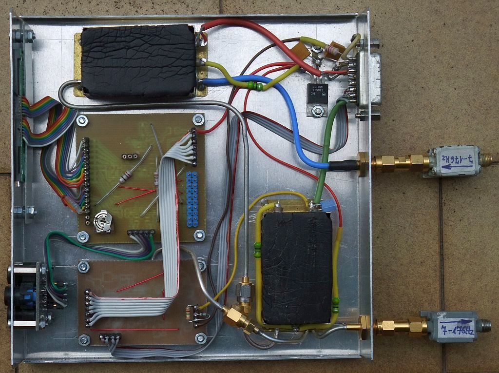
In order to avoid unwanted reflections, both antennas are connected to the RF head through ferrite isolators (circulators with the third port terminated). All of the remaining components of the RF head are installed in an 150mmX150mmX30mm box made of 1.0mm Al sheet:
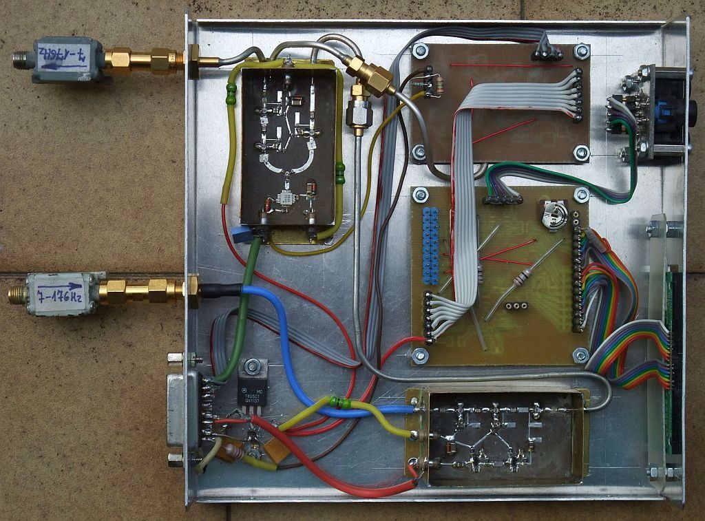
All covers and shields are removed on the following picture:
The RF transmit signal sweeping across the 10240MHz-10272MHz frequency band originates from a wideband VCO HMC732 made by Hittite. The latter originates from a different previous project and its phase-noise performance is not the best. The sensitivity range of an updated FMCW radar could benefit from a silicon VCO chip covering a narrower frequency band with approximately 20dB better phase noise!
The HMC732 VCO output signal level is quite low around 1mW and is split further with a resistive wideband divider. The transmit buffer amplifier includes two ATF35076 HEMT-amplifier stages to obtain +15dBm (around 30mW) of transmit power. The latter is limited by the unwanted crosstalk between the transmitting and receiving antennas. Part of the transmit signal drives the HMC702 fractional PLL with -5dBm through a resistive divider. The receive mixer requires about +5dBm obtained from a separate ATF35076 HEMT-amplifier stage:
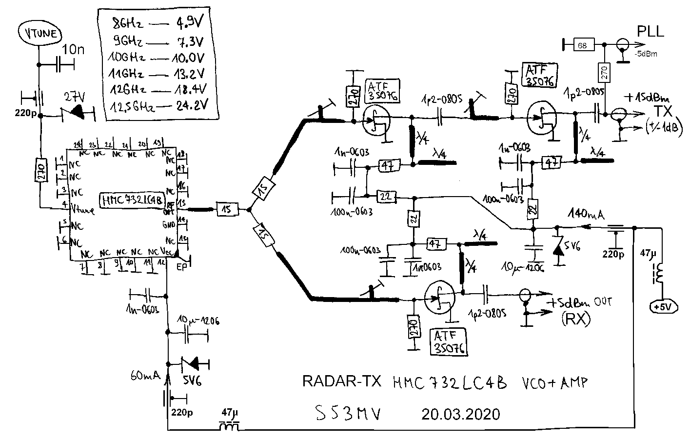
The VCO module is built as a microstrip circuit on an Ultralam2000 woven-teflon printed-circuit board with 19mils (0.5mm) thickness and specific dielectric constant of 2.43. The other side of the teflon board is not etched to act as a groundplane. All of the components are grounded through 3.2mm holes drilled in the substrate. Most holes are covered with 0.1mm-thick tinned sheet on the ground side. The -5dBm output is not present on the PCB pattern since it was added later:
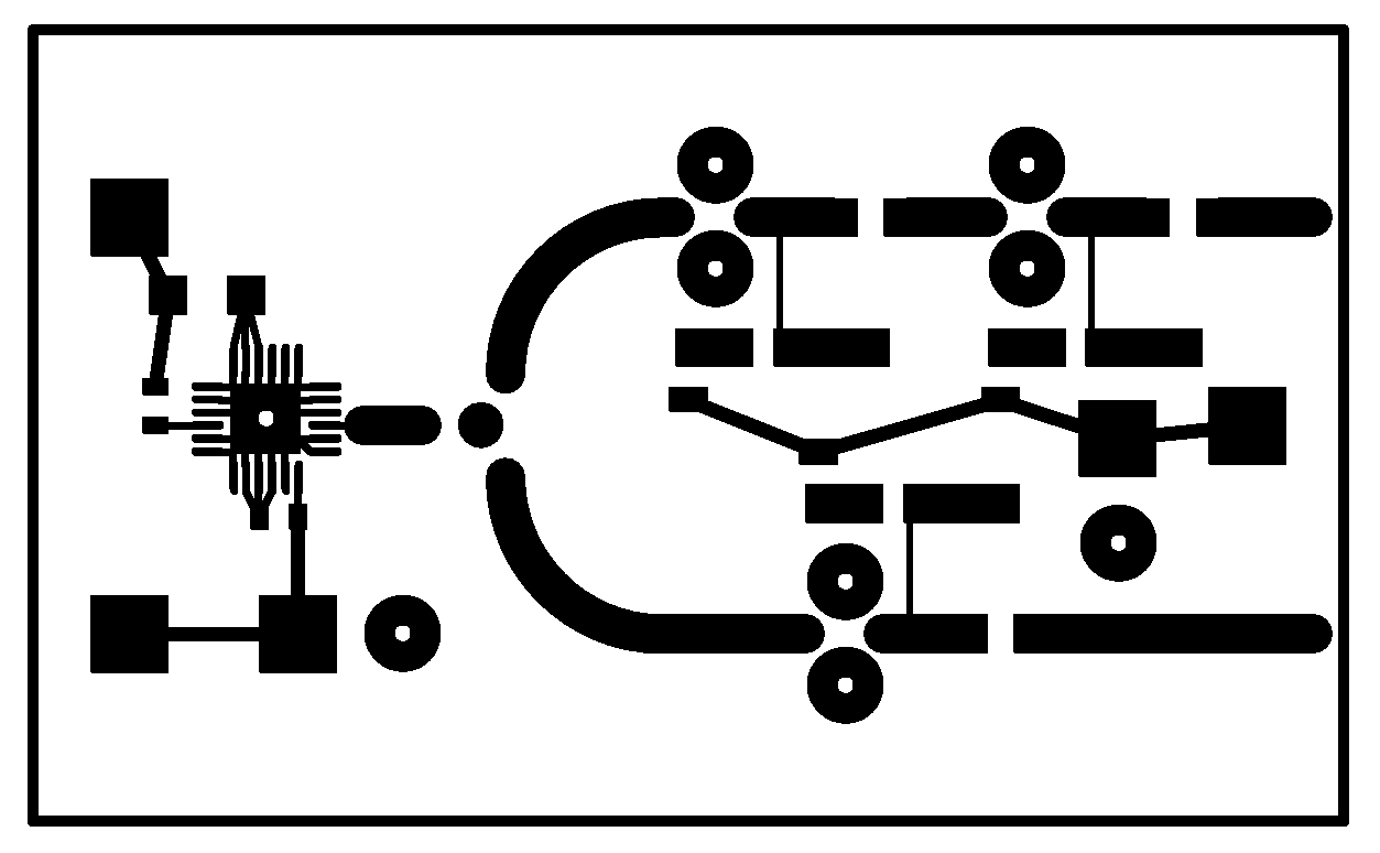
The VCO module 30mmX50mm is then soldered into a frame made from 0.3mm-thick brass sheet. The frame is 20mm wide, the microstrip board is soldered 5mm above the bottom while the feedthrough capacitors are installed 10mm above the bottom. There is no metal cover, but the brass box is later covered by a 10mm-thick piece of microwave-absorber foam:
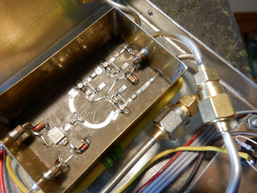
The frequency of the HMC732 VCO is controlled by a HMC702 third-order fractional PLL. The output frequency is referenced to a 32.000MHz TCXO although the first experiments were done with a 100.0MHz oscillator. The charge-pump output of the HMC702 with 3.3V supply is then amplified to the whole 0-24V range as required by the HMC732 VCO. A high-speed operational amplifier like the AD847 or better AD797 is required for the latter function.
The stability of the PLL is obtained through the lead-lag network 47pF+390ohm+68nF that includes the parasitics of the operational amplifier. The latter is the only circuit in the RF head operated with a supply voltage of +24V DC. All the other circuits of the RF head are operated directly at +5V DC or further reduced down to +3.3V DC. All inputs and supply voltages in all modules are protected from overvoltages with suitable zener diodes:
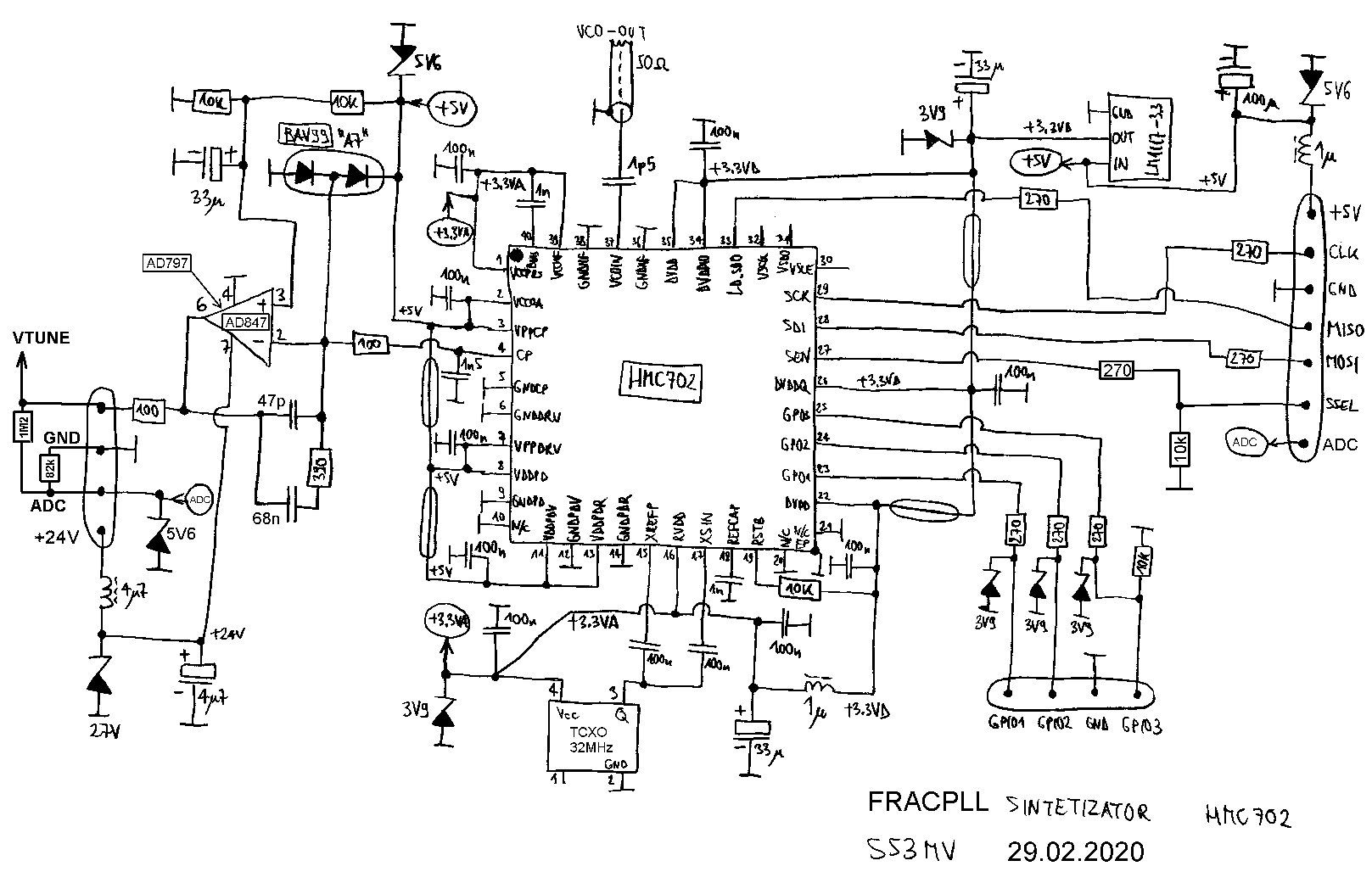
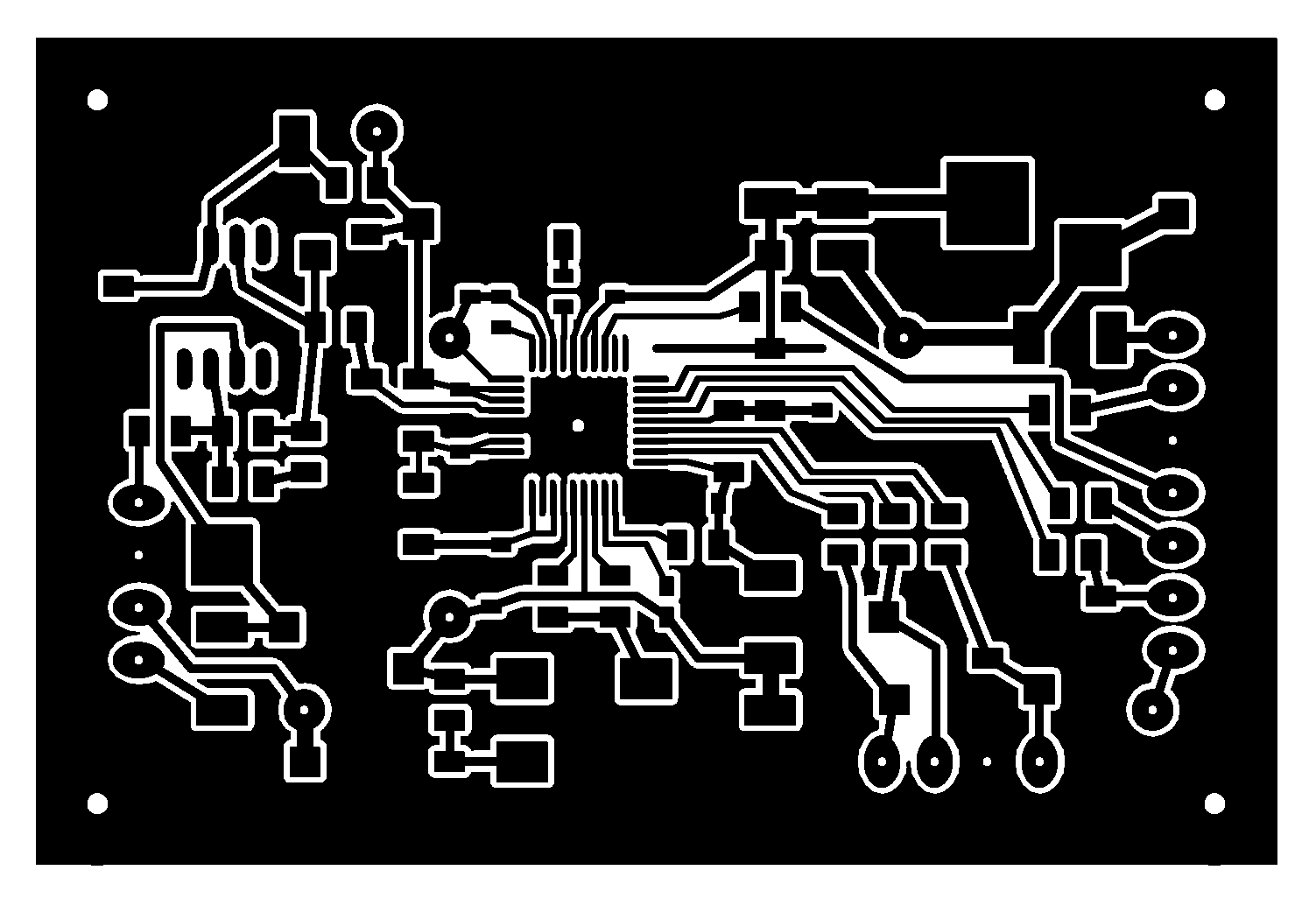
The third-order fractional PLL and related components are installed on a single-sided printed-circuit board etched on 1mm-thick FR4 laminate with the dimensions of 60mmX40mm:
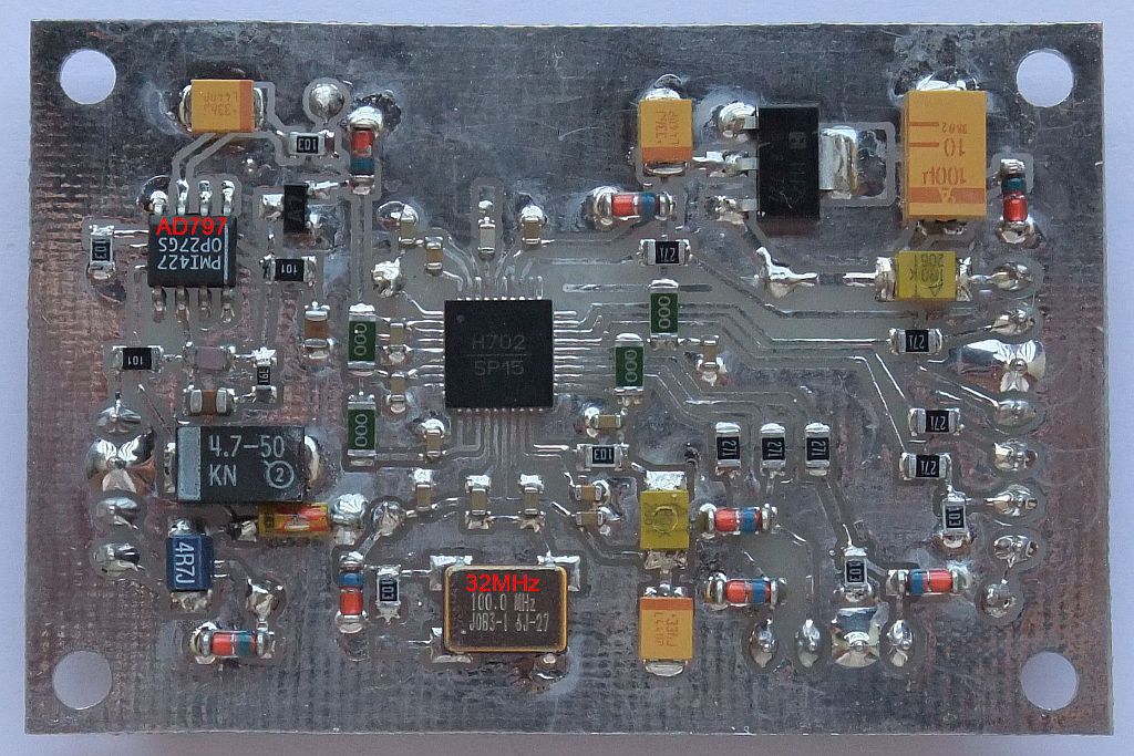
The PLL module also includes a voltage divider 1M2+82k used to monitor the VCO control voltage through the A/D converter installed in the microcontroller. The component side of the PLL module shows some components from earlier versions like the 100.0MHz XTAL oscillator or the OP27 amplifier found later to be too slow for this application:
The HMC702 third-order fractional PLL is controlled by several 24-bit regiters. The latter are programmed via a three-wire serial interface SCK, SDI and SEN. Register reads are performed through the serial output LD_SDO. All data transfers begin with a RD/WR bit, followed by six register address bits and end with 24 data bits to be either read or written.
An external microprocessor is therefore required to initialize or modify the contents of some registers and read the results, both done through a standard SPI port. Signals requiring immediate action are also available on the GPO1, GPO2 and GPO3 pins. The HMC702 further includes a sweep generator allowing bidirectional linear frequency sweeps between preset values, very useful for FMCW radars.
The HMC702 third-order fractional PLL is programmed with a LPC2318 microcontroller. The latter is overspecified including a 32-bit ARM core and several peripherals. The same functions could be provided by a much simpler 8-bit PIC or similar. The microcontroller also drives a 2X16 character LCD display through its built-in HD44780 controller. The PLL parameters are set through four pushbutons: LEFT, UP, DOWN and RIGHT and are usually stored in the FLASH memory of the microcontroller:
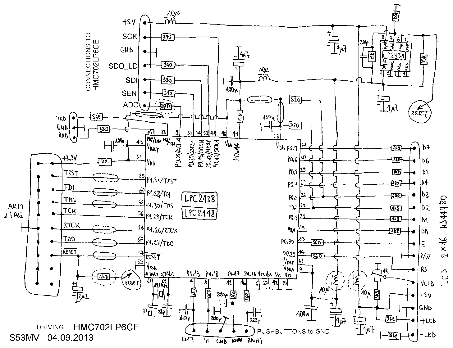
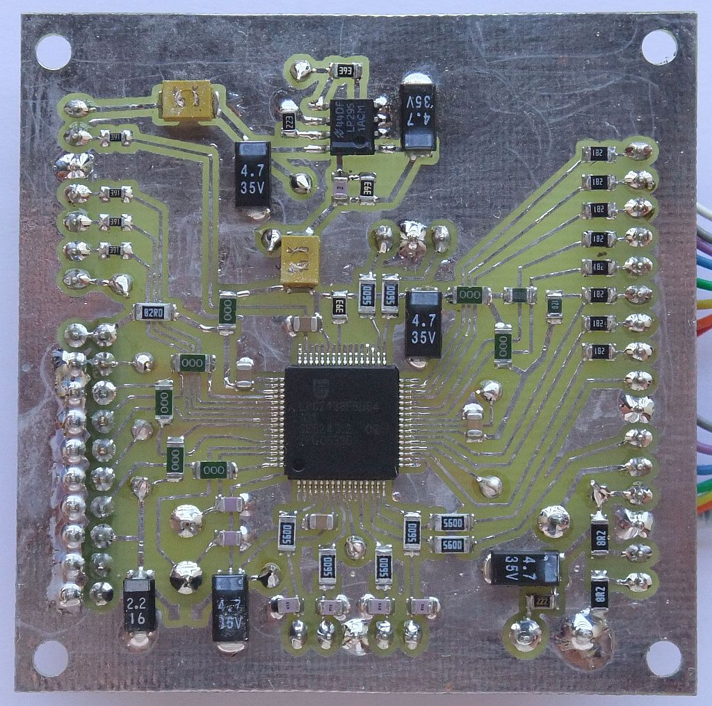
The microcontroller is assembled on a 60mmX60mm FR4 single-sided printed-circuit board. A smaller 30mmX30mm FR4 printed-circuit board carries the four pushbuttons:
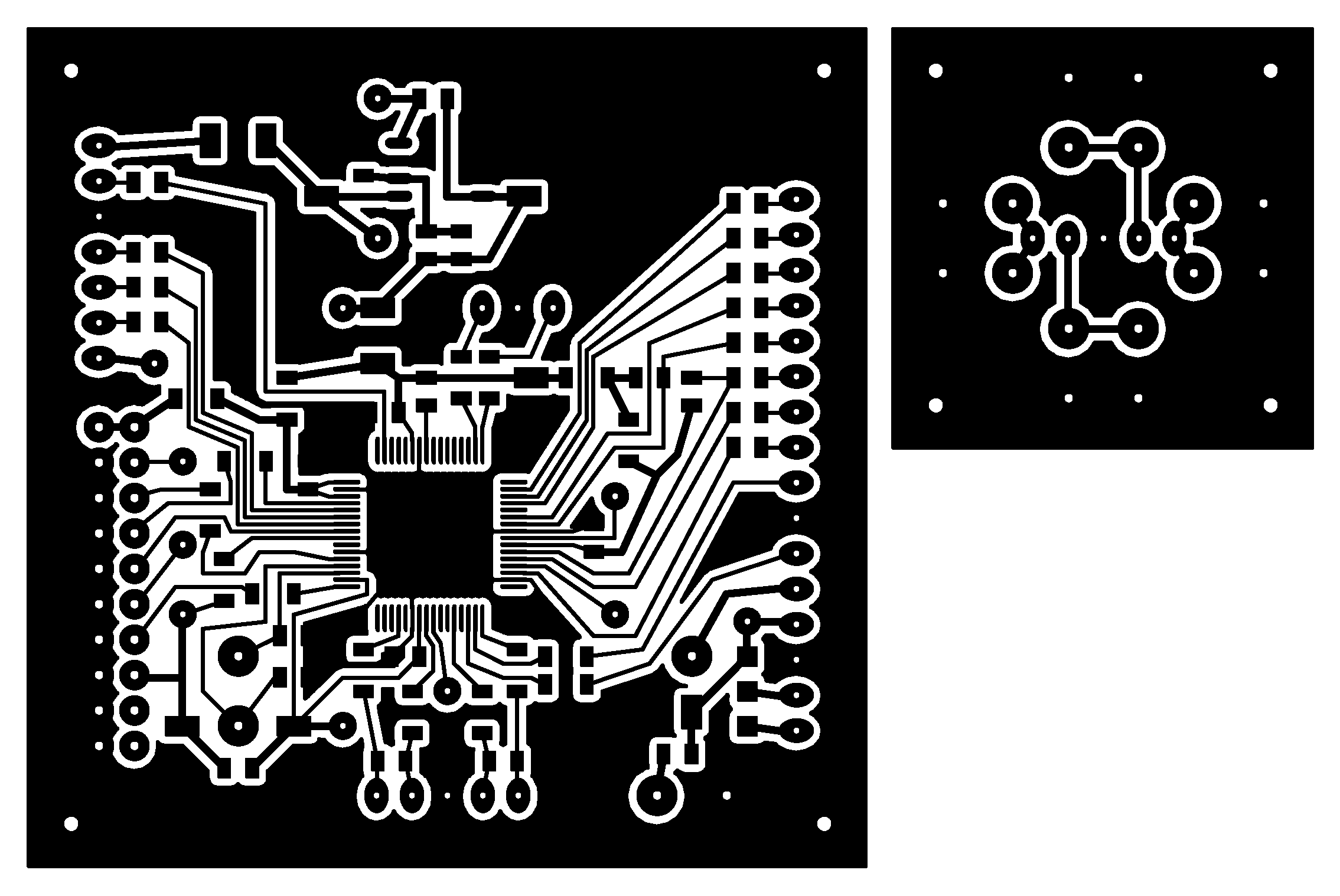
The assembled microcontroller includes a 5-pin connector for the pusbuttons, a 7-pin connector for the PLL, a 16-pin connector for the LCD mudule and a 20-pin connector for a standard ARM JTAG programmer to load the PLL firmware:
It makes sense to issue a RESET command to the HMC702 third-order fractional PLL first. Most of the remaining HMC702 registers may be programmed in an arbitrary order. The only exception is the register 0x14. This has to be programmed last and many times to start the bidirectional sweep correctly.
After RESET the microcontroller allows to write selected registers in four passes. Pass#0 sets all non-critical registers. Pass#1 and pass#2 are used to start the bidirectional sweep by programming register 0x14 twice:

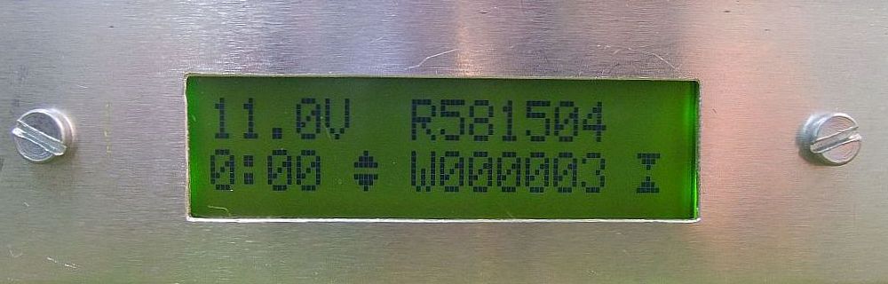
All parameters are shown on a 2X16 alphanumeric LCD. The top line of the display shows the measured VCO voltage first with one decimal place in volts. The hexadecimal value read from the selected register R is displayed next. Finally an "unlock" status of the PLL may be displayed.
The bottom line of the display shows the pass# number 0, 1, 2, or 3 first followed after the colon by the selected register hexadecimal number. The up/down arrows copy R>W or W>R. The selected value to be written is shown after W. Finally the write status is selected ON (symbol) or OFF.
The UP and DOWN keys modify the parameter shown by the blinking cursor. The LEFT and RIGHT keys select the parameter to be modified. A simultaneous depression of LEFT+RIGHT writes the selected parameters into the microcontroller EEPROM to be used on the next and all following RESETs:
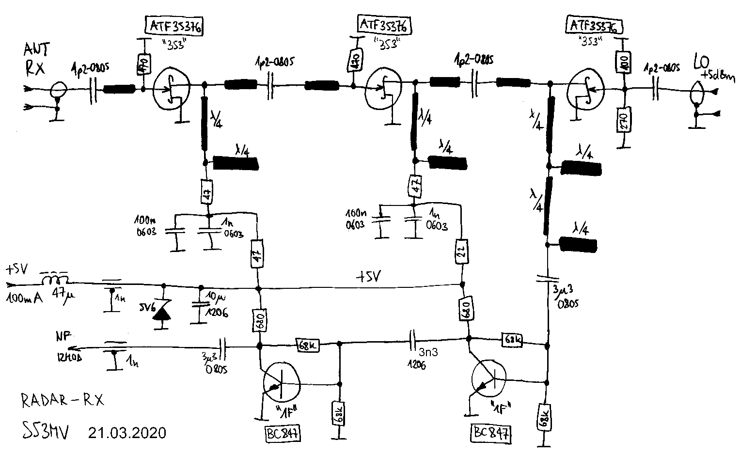
The receive downconverter obtains the FMCW beat 0.2-48kHz by mixing the returning signal with the same local oscillator. To improve the receiver sensitivity, two ATF35376 HEMT RF amplifier stages are used. There are no RF bandpass filters, since bandpass filtering introduces group delays therefore making the unwanted antenna crosstalk worse. Since the gain of HEMT amplifiers does not increase much at lower frequencies unlike bipolar transistors, no additional filtering is required.
The third ATF35376 HEMT is used as a balanced passive mixer. The FMCW beat is then amplified by two low-frequency bipolar transistors BC847. The interstage coupling is only 3.3nF to provide a linear high-frequency boost (preemphasis) to compensate the signal loss at increasing range. Beat frequencies below 200Hz are further attenuated by the 3.3uF input capacitor to attenuate the antenna-crosstalk beat:
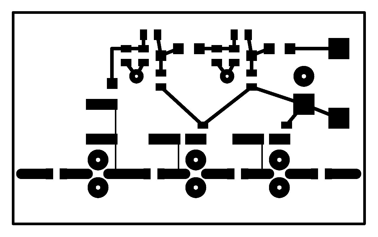
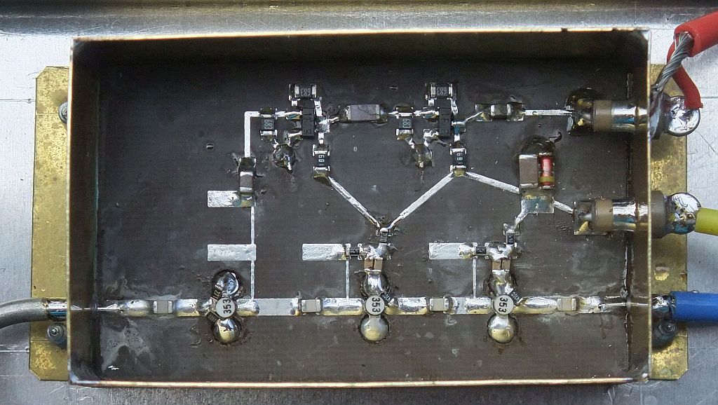
The receive downconverter is built as a microstrip circuit on an Ultralam2000 woven-teflon printed-circuit board with 19mils (0.5mm) thickness and specific dielectric constant of 2.43. The other side of the teflon board is not etched to act as a groundplane. All of the RF components are grounded through 3.2mm holes drilled in the substrate. Most holes are covered with 0.1mm-thick tinned sheet on the ground side. The FMCW low-frequency beat amplifier is grounded through 1mm holes:
The downconverter module 30mmX50mm is then soldered into a frame made from 0.3mm-thick brass sheet. The frame is 20mm wide, the microstrip board is soldered 5mm above the bottom while the feedthrough capacitors are installed 10mm above the bottom. There is no metal cover, but the brass box is later covered by a 10mm-thick piece of microwave-absorber foam:
The RF head includes two SMA connectors for both the transmitter output and receiver input. Both are equipped with external ferrite isolators (circulators) suitable for operation at 10GHz:
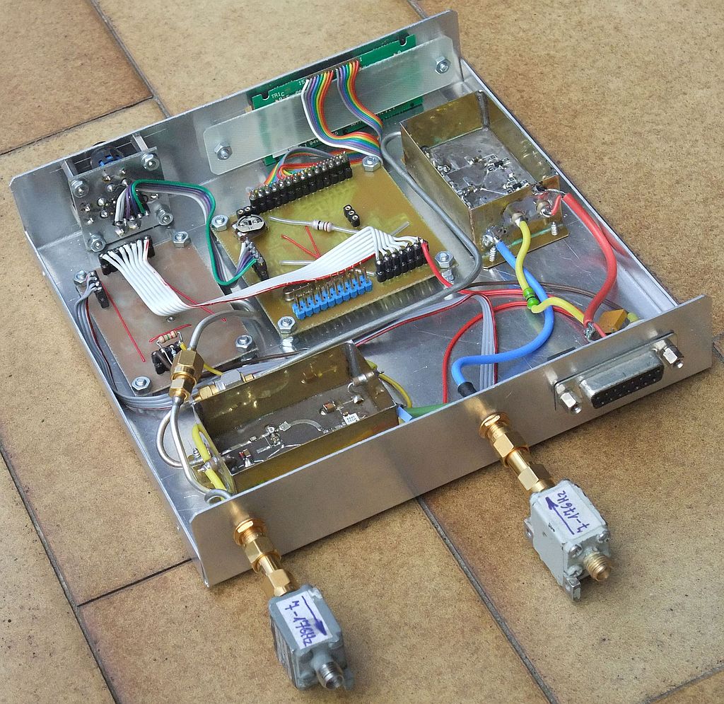
All the low-frequency connections are made through a single DB-15 connector: the 24V external power supply,the downconerter 0.2-48kHz beat output, the VCO control voltage and the GPO0/1/2 signals. The VCO control voltage and GPO0/1/2 signals are provided for test purposes only, they are not used in the operational FMCW radar. An audio-grade shielded cable feeds the 24V power and 0.2-48kHz beat output to the indoor computer.
In order to use the MIC input of a standard computer audio card, the most efficient solution found is a 47kohm series resistor. To avoid picking unwanted audio noise, the latter is best installed close to the audio card, therefore at the end of the cable from the outdoor RF head.
An internal +5V DC supply regulator is used for most circuits of the RF head:

Considering the operating frequency of the RF head around 10GHz, it is impossible to build the metal cases small enough to avoid internal resonances. Therefore microwave absorber foam is fitted on top of both VCO and downconverter modules. No additional shielding is required of the individual modules while the overall Rf head enclosure uses a cover from standard 0.6mm thick Al sheet:
(RADAR) (RF-HEAD) (ANTENNAS) (PROCESSING) (WEATHER) (HOME)