(RADAR)
(RF-HEAD)
(ANTENNAS)
(PROCESSING)
(WEATHER)
(HOME)
Homemade FM weather radar at 10GHz
Matjaz Vidmar, S53MV
3. Antennas
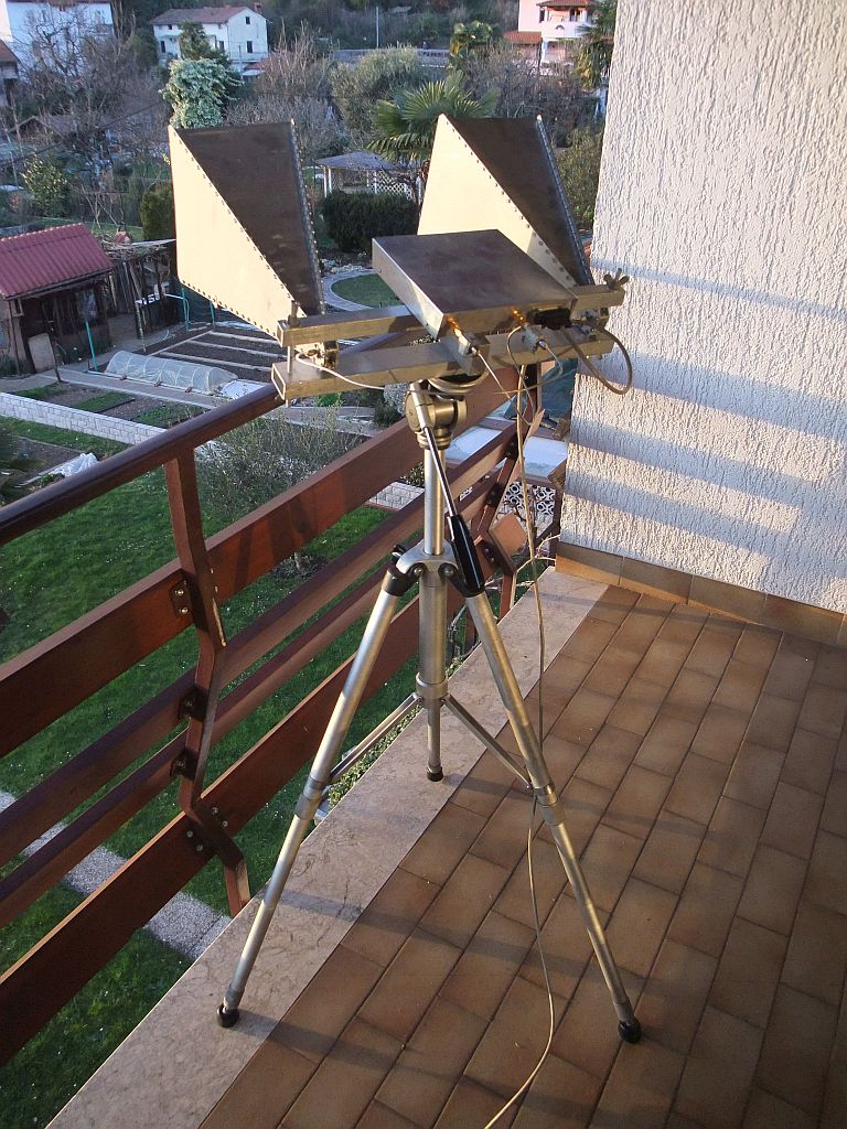
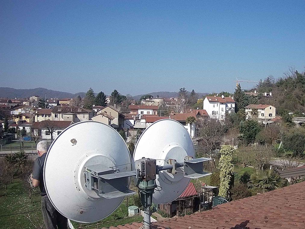
The FMCW radar was tested with two identical 23dBi pyramidal horn antennas first. Both antennas are oriented in the same direction on a common support with horizontal polarization. The main advantage of horn antennas are very low sidelobes and therefore little crosstalk. The latter is a limiting parameter in a FMCW radar:
The common antenna support could be hand steered both in azimuth and elevation:
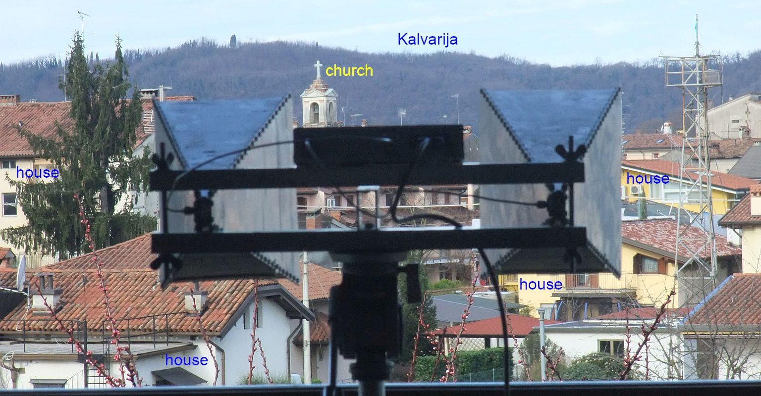
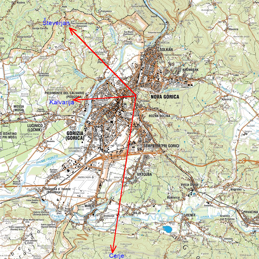
Objects in the field of view of the antennas could be clearly identified ranging from nearby houses up to the mountain Kalvarija at the distance of almost 3km:
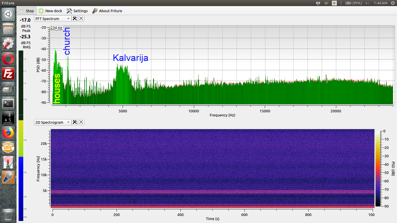
The FMCW radar beat was sent to the sound card of a standard desktop computer. The spectrum of the 0-24kHz FMCW beat signal was analyzed with the readily-available spectrum-analyzer software "Friture". The reflection from a relatively small target as the church tower generates a much narrower spectrum than the sum of reflections from different houses and the many more trees on the distant mountain:
The map of many visible objects from the location of the FMCW radar is shown here:
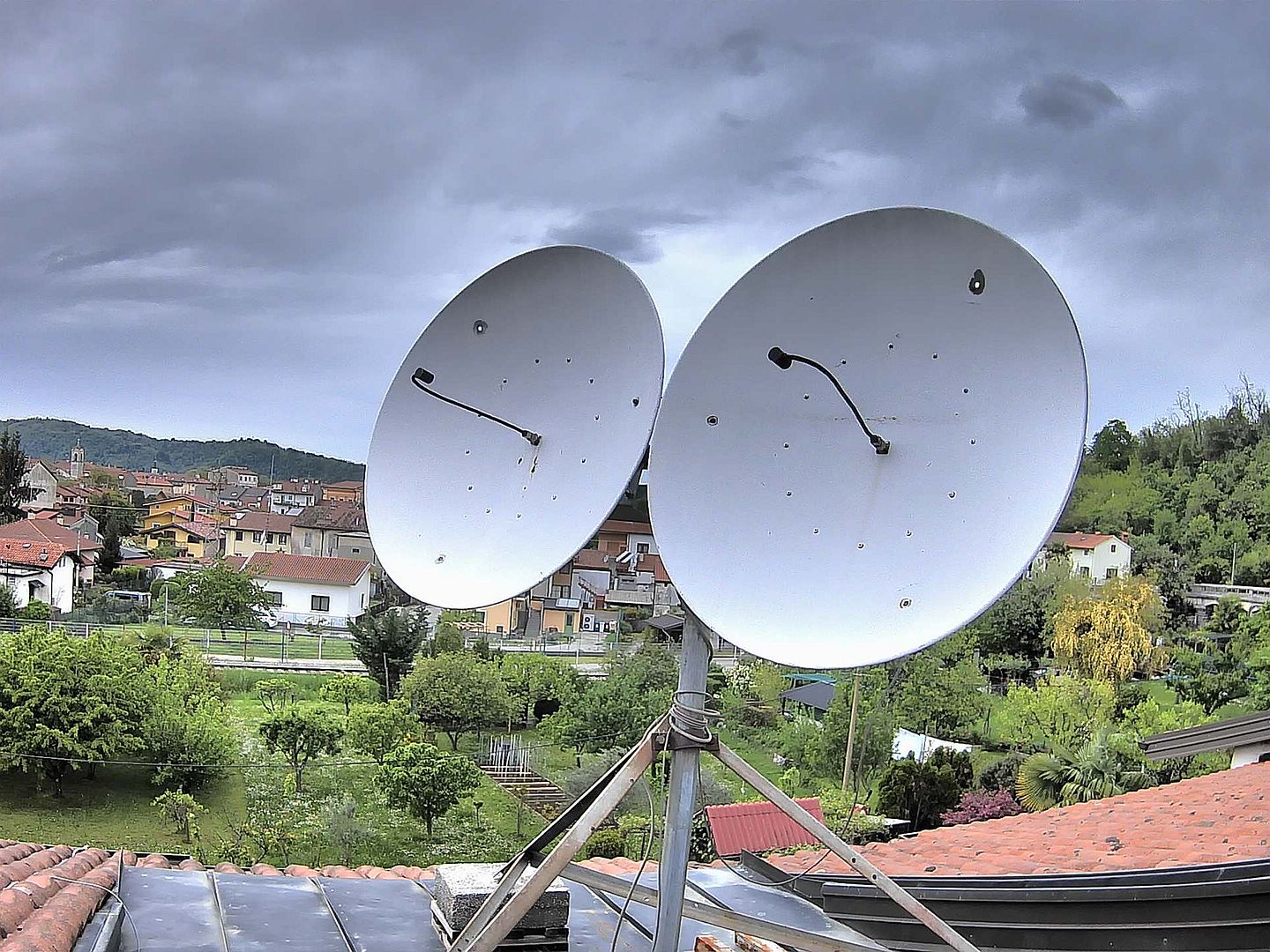
Encouraged by the success with relatively small horn antennas it was decided to install two larger antennas on a mechanical rotor KR5600 allowing both azimuth and elevation adjustment at the same time:
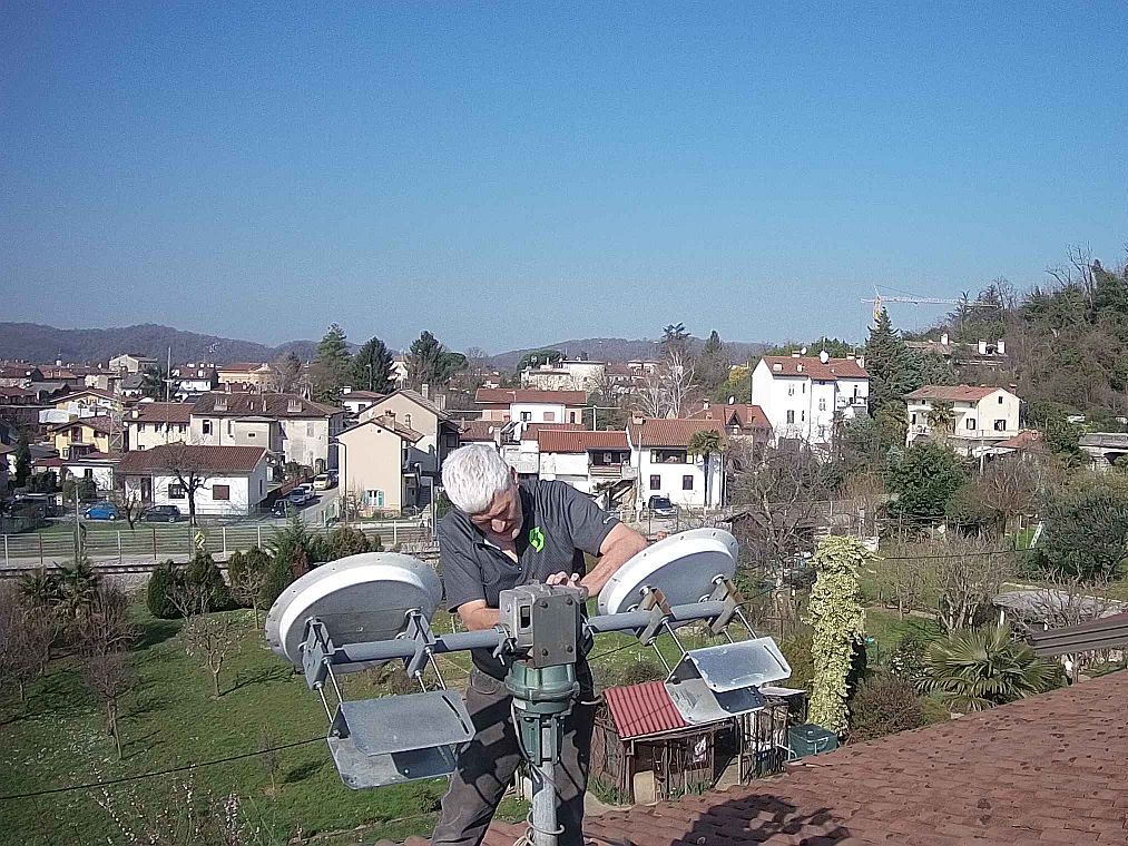
The antennas selected were two identical parabolic dishes of 90cm diameter each, corresponding to 30 wavelengths at 10GHz (the maximum allowed by the KR5600 mechanical strength). Counterweights and fins are used to reduce the wind load on the KR5600 rotor. Both antennas should always remain pointed to exactly the same location:
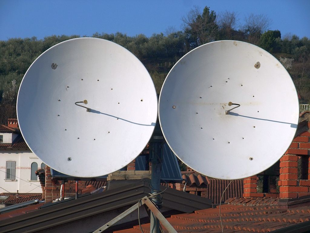
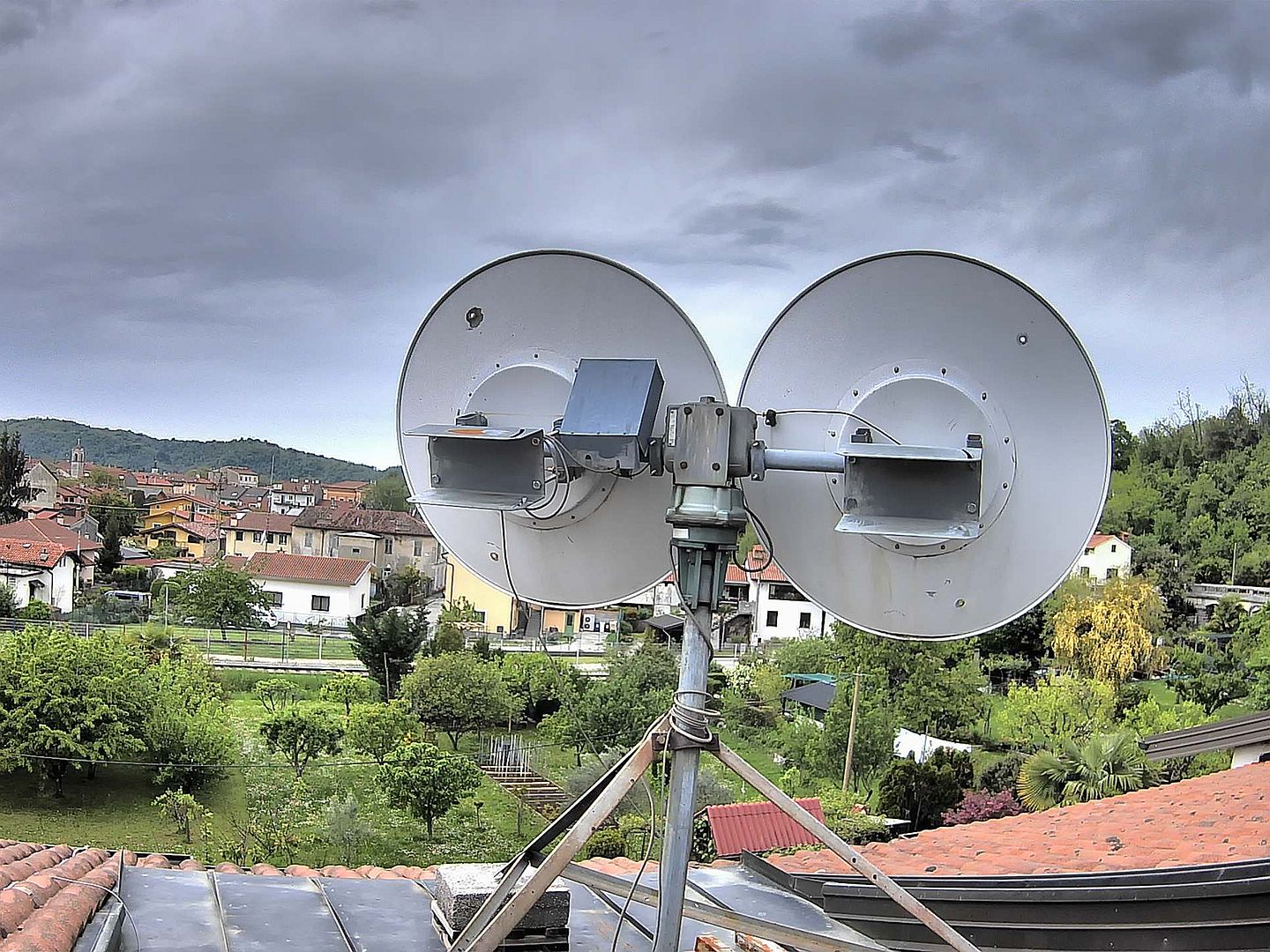
Each dish is fed by a simple circular-waveguide horn, fed and supported by 1/4" semirigid cable for an estimated gain of around 38dBi. Horizontal polarization is used to maximize back reflection from oblate raindrops. The waveguide horn is filled with styrofoam (expanded polystyrene foam) that is transparent to microwaves but reduces the effects of water on the antenna:

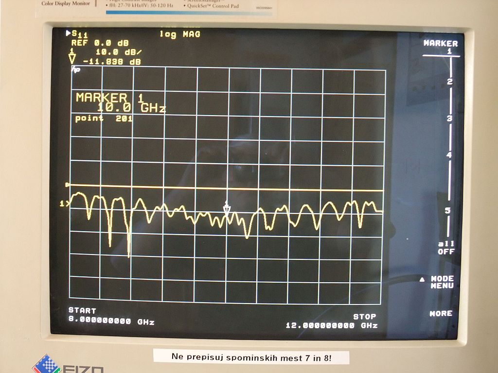
The simple feeds achieved a return loss of around -10dB mainly due to the many connectors in the feed network. Due to the imperfect antenna impedance matching, ferrite isolators were used both on the transmitter output as well as on the receiver input:
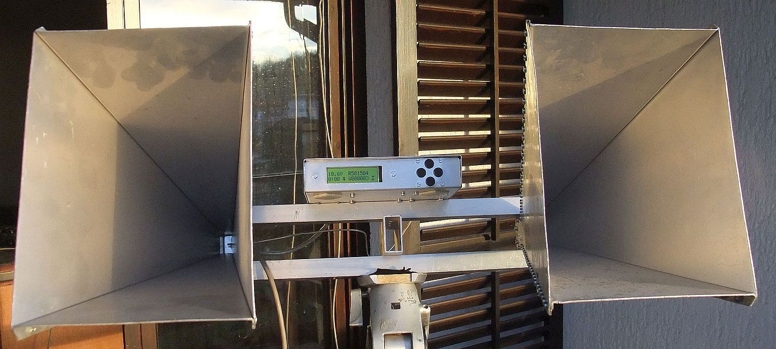
The original rotor controller was used with the KR5600, connected to the latter via a multipole cable:
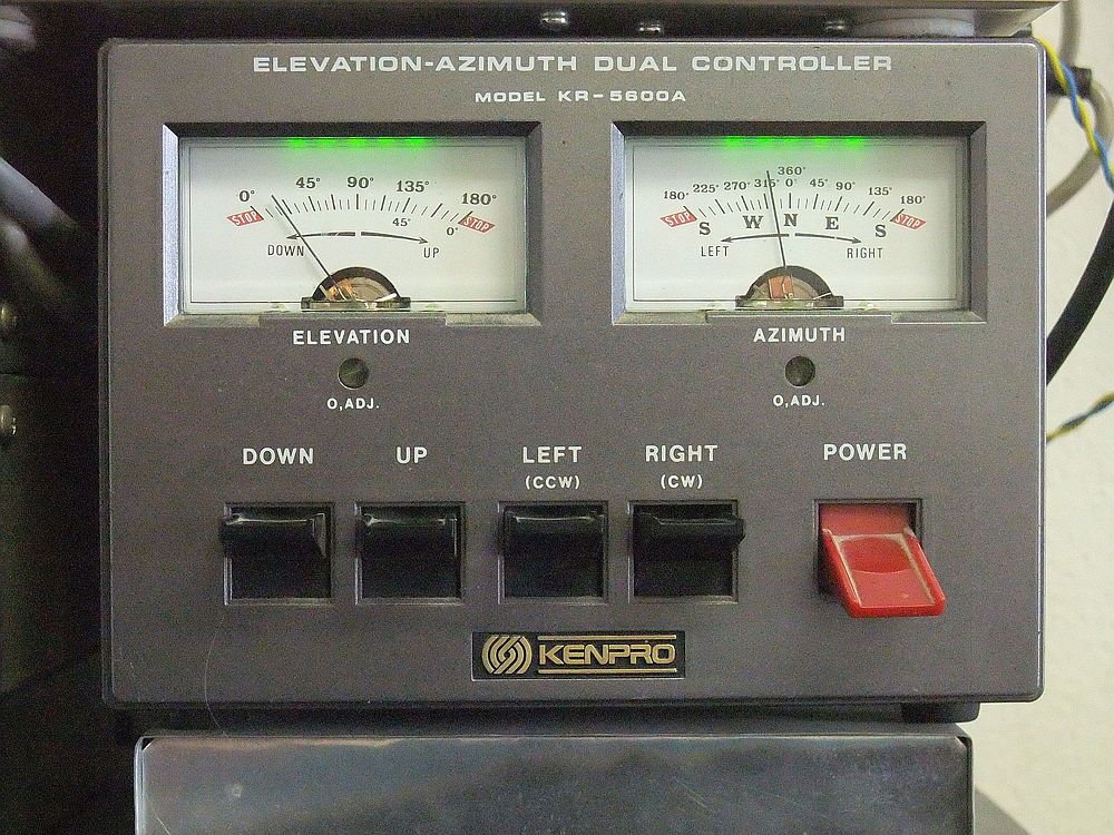
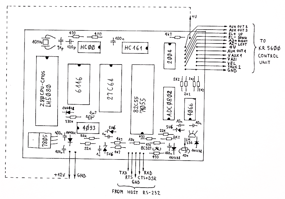
The rotor controller provides two analog voltages VAZI and VEL and accepts four digital signals UP, DOWN, LEFT and RIGHT (open collector). The analog signals are evaluated and the commands are sent from an RS-232 interface:
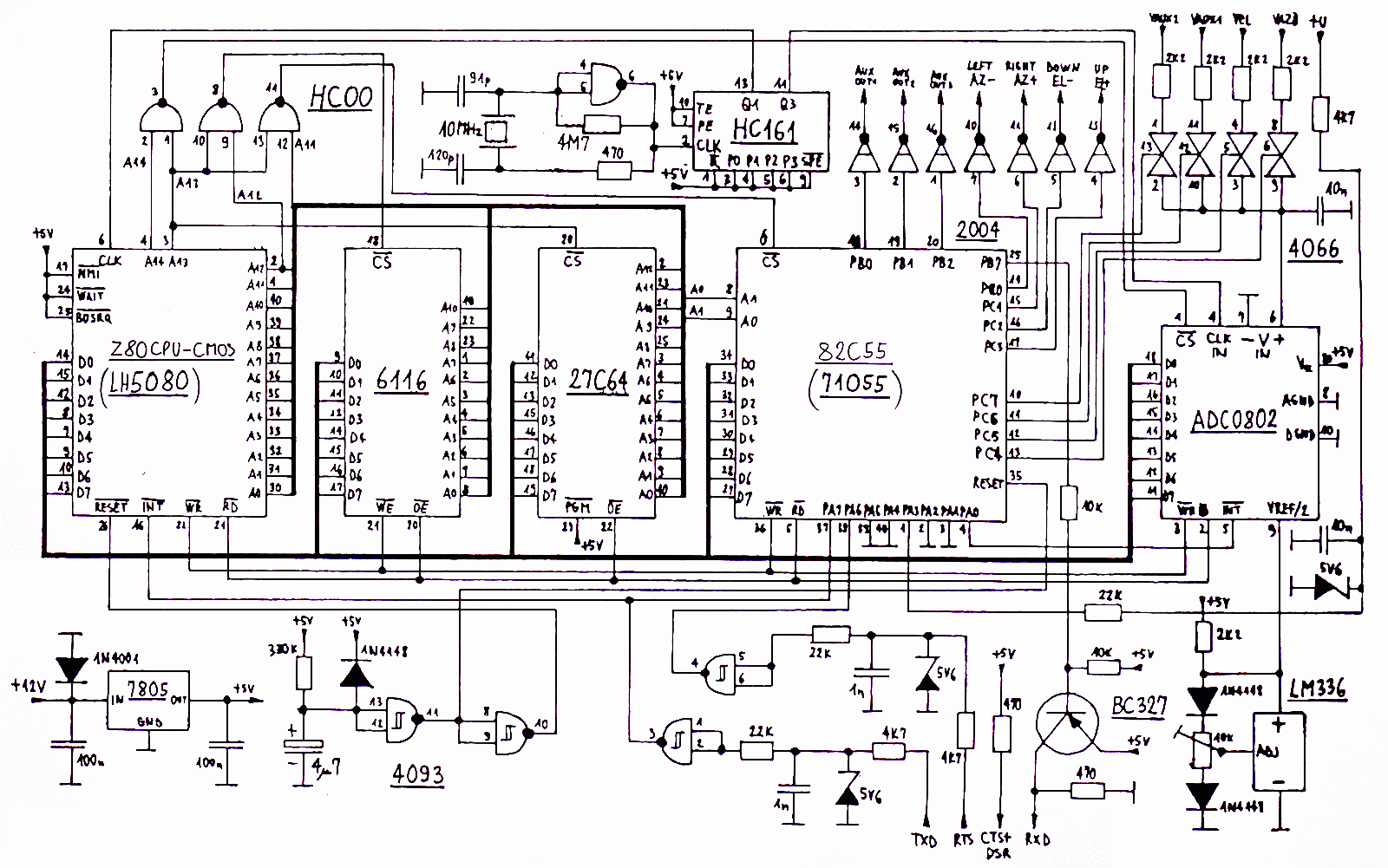
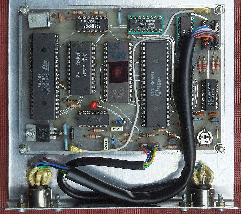
The RS-232 interface includes a Z80 microprocessor and an ADC0802 8bit A/D converter.
KR5600.zip It was originally designed and built back in the age of 8-bit microprocessors to steer the KR5600 for automatic satellite tracking:
The RS-232 is implemented in software inside the Z80 CPU and operates at 9600 baud in both directions. The resistor in series with the handshake line is reduced to 120ohm to supply a RS-232 isolator from the latter:
The RF head including ferrite isolators was initially placed behind the two antennas. Only the low-frequency beat signal output and the +24V supply voltage are fed to the indoor units through a shielded cable:
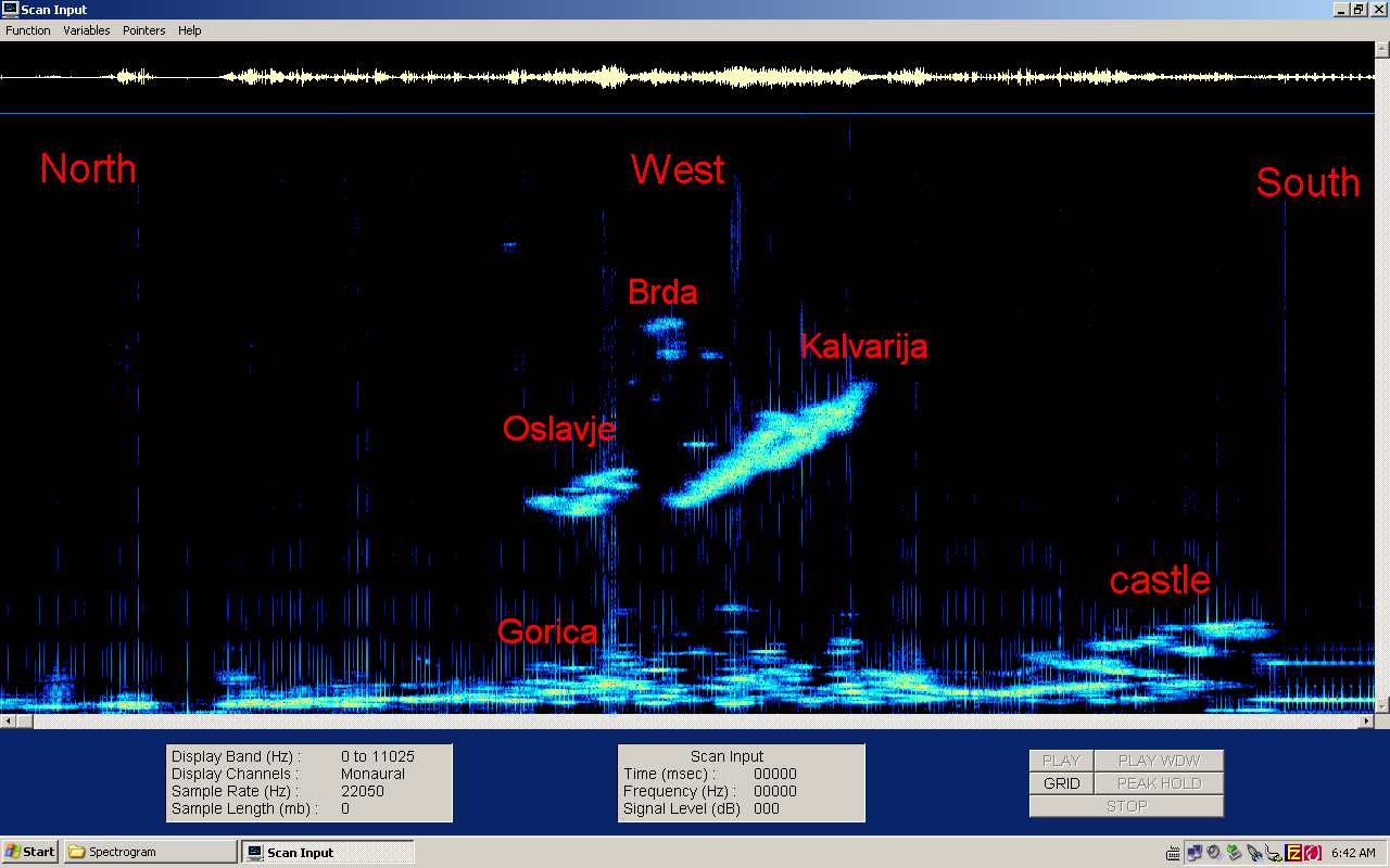
The first scan of the new antenna North-West-South with the software "Spectrogram":
The assembled FMCW radar is shown on the following picture:
The RF head is placed inside a watertight case behind the antennas and rotates in both azimuth and elevation with the latter:
(RADAR) (RF-HEAD) (ANTENNAS) (PROCESSING) (WEATHER) (HOME)