(RADAR)
(RF-HEAD)
(ANTENNAS)
(PROCESSING)
(WEATHER)
(HOME)
Homemade FM weather radar at 10GHz
Matjaz Vidmar, S53MV
1. Weather radar
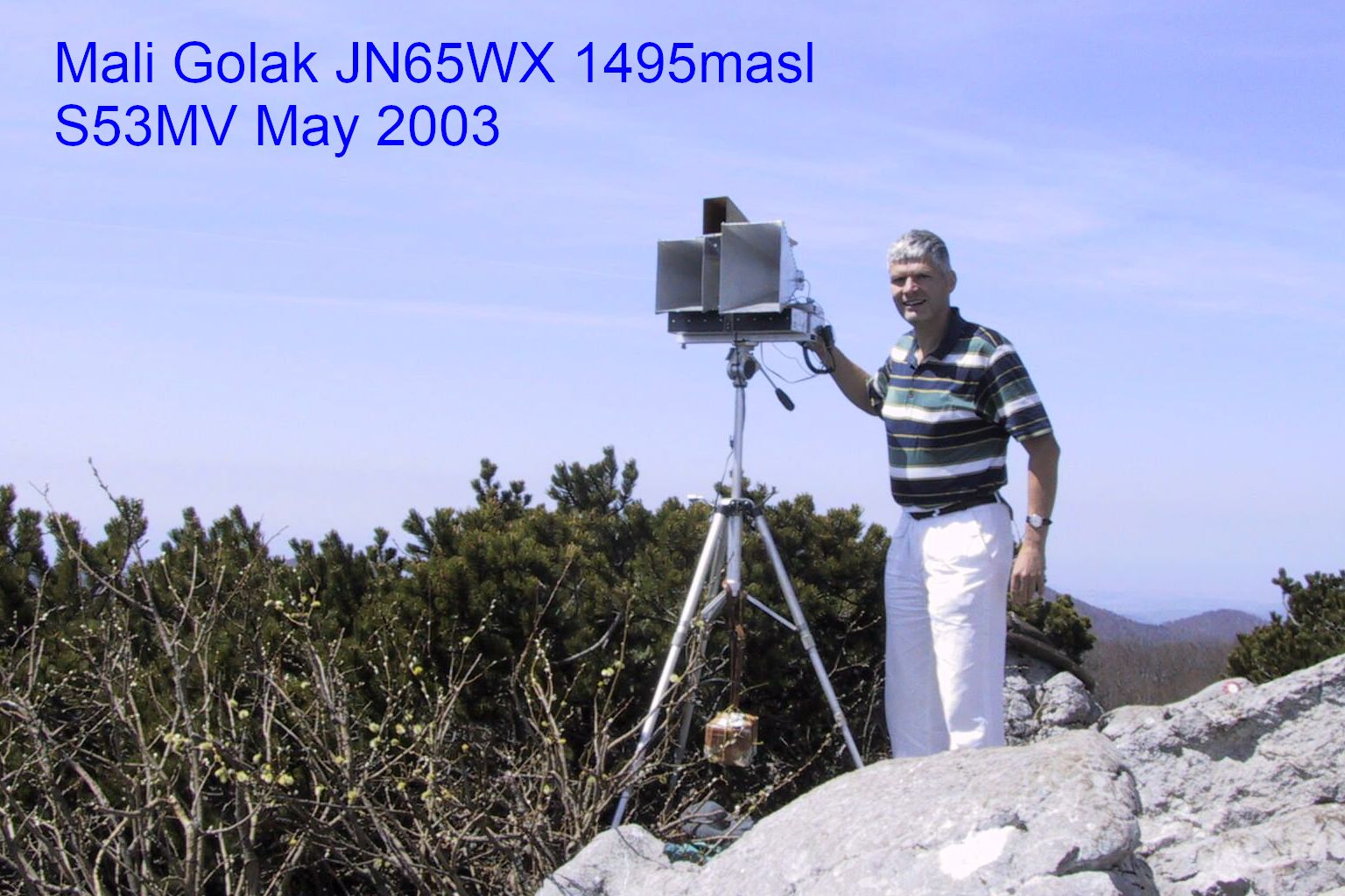
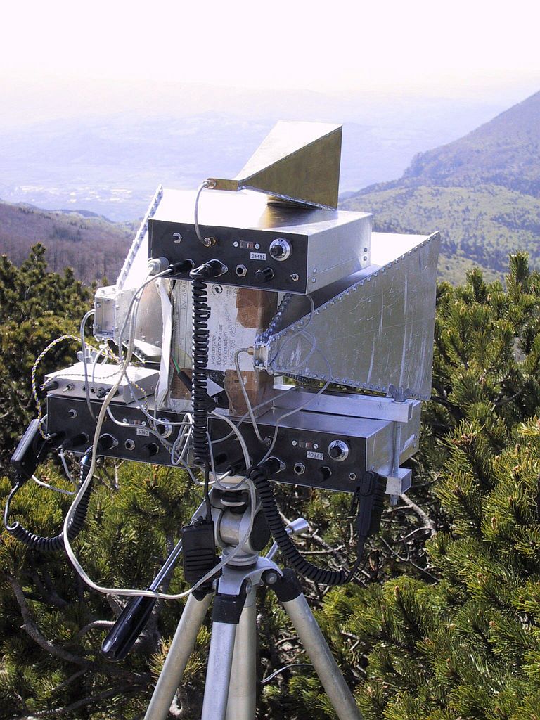
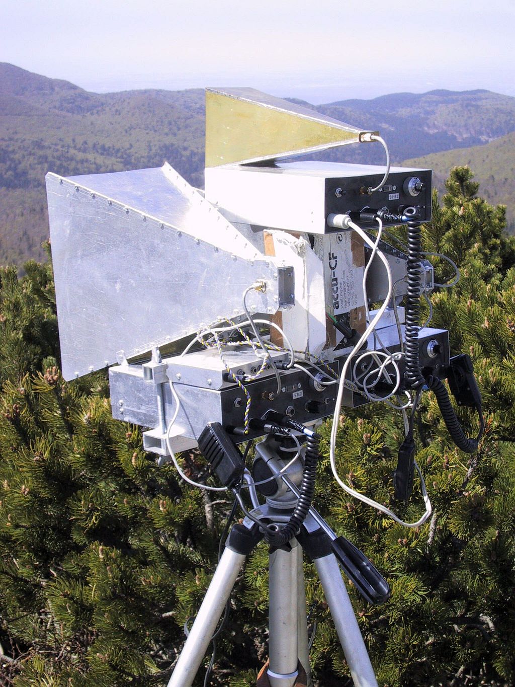
Unlike other articles on this webpage a successful experiment using many types of different existing equipment is described here. The experiment is based on observations using communication-grade ham-radio equipment many years ago, in particular equipment for microwave frequency bands. All of my equipment was based on Weaver or ZIF-SSB radios using a frequency offset of 1365Hz (=32768Hz/24). All of the equipment was always operated battery powered from different mountain tops. Horizontally-polarized horn antennas were used on 5.7GHz (20dBi), 10GHz (23dBi) and 24GHz (25dBi):
Using the described equipment, several bidirectional SSB contacts using reflections from thunderstorm clouds were possible using just 100mW of power at 10GHz. In addition Doppler shift could be observed as the frequency difference between the direct signal and the reflection from thunderstorm clouds by turning my antenna in the appropriate directions. Unfortunately fewer experiments were done at 5.7GHz due to lack of interested correspondents. Even worse at 24GHz where half of the correspondents usually did not have their equipment for 24GHz in working order.
Since WWII the water-vapor absorption band around 22GHz is well known to reduce the range of K-band radar. The same water-vapor absorption also decreases the range of any amateur-radio contacts at 24GHz. On the other hand, the Rayleigh scattering from raindrops is about 15dB stronger at 24GHz when compared to 10GHz.
At 24GHz excellent frequency stability is required for SSB operation. My radio improved a lot by replacing a 28MHz computer-grade crystal with a top-quality crystal from Institute Mihailo Pupin in Beograd. Unfortunately in the meantime my amateur-radio correspondents shifted for unknown reason form 24192MHz to 24048MHz for narrow-band SSB operation. The latter required a new crystal for my radio that I could not obtain. My experiments on 24GHz ceased thereafter.
Besides advantages a Weaver SSB radio also has drawbacks. Local-oscillator leakage causes Doppler shift while waving your hand in front of the antenna. The latter can be heard as a 1365Hz tone in the described Weaver radios.
On several occasions but not always a continuous 1365Hz whine could be heard from almost all directions with apparently no moving objects close to the antenna. Occasionally quite strong and disturbing. Present on all frequency bands form 1.3GHz up to 10GHz. Very seldom heard at 24GHz. Initially I had no explanation for the described effect.
The cause of the 1365Hz whine was finally found as the local-oscillator leakage reflected from raindrops. The latter need not be local. The rain cloud may be at considerable range. Cloud movement caused Doppler shift so that the 1365Hz tone can be heard as a continuous whine in a Weaver SSB receiver. The bottom story is that weather radar is well within range for amateur radio. Very high transmitting power is not required to detect rain and measure rain intensity. Modest-size antennas are acceptable for the range limited to about 25km due to earth's curvature.
Radar is commonly associated with the detection of aircraft. WWII technology allowed peak pulsed transmitter powers around 100kW at 3GHz. The average radar transmitting power may be 1000 times smaller. The design of the radar is mono-static using the same antenna for both transmission and reception. The radars range is further limited due to earth's curvature to about 300km for high-flying aircraft and much less at lower altitudes.
The intensity of the reflection is described by the radar cross-section "sigma". The latter may be very high, much larger than the object itself, for cooperating targets like flat plates and/or retroreflectors. In any case, the reflection from a relatively small target (aircraft) decreases with the fourth power of its range (r**4):

Most aircraft scatter the incoming radar signal in many directions. In the latter case the radar cross-section is of the same magnitude as the real physical cross-section of an aircraft. A large metal sphere r>>lambda scatters the incoming signal uniformly in all directions. Its radar cross-section can be calculated from the Fresnel zones due to sphere curvature. The radar cross-section of a large metal sphere is identical to its mechanical cross section pi*r**2.
The radar cross-section of an aircraft can be approximated by replacing its structure with several metal spheres. Low-radar-visibility aircraft have sharp edges to minimize the reflection back to the radar. Even these aircraft are vulnerable to radar from some directions like from below the aircraft.

A pulsed radar is not the only technical solution for a radar. Other solutions can be used if separate transmitting and receiving antennas are available. In particular it may be difficult to generate high peak powers for very short pulses as required for short-range and/or high-resolution radars. Since both transmitter and receiver operate all of the time, unwanted cross-talk between the two corresponding antennas may be a limiting factor.
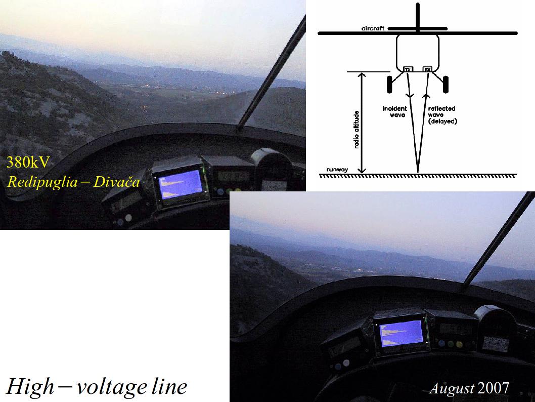
The cross-talk interference may be mitigated by using a continuous transmission in a FMCW radar. An aircraft radar altimeter is usually designed as a FMCW radar in the 4.3GHz band. More recently automotive radars are usually designed as FMCW radars operating in the 77GHz band.

Interestingly a low-power, tiny FMCW radar can see much more than just the reflection from ground. Overflying a 380kV high-voltage line the reflection from the wires high above ground can easily be seen:
For speed measurement only, a CW Doppler radar may be used. Unfortunately it is difficult to separate speed from range in a FMCW radar, especially when both effects are of similar magnitude.

The Doppler effect is frequently used to separate moving targets like an aircraft from the much stronger reflection from the nearby ground. Note that in a pulsed radar, the Doppler signal in not available continuously but it is sampled at the repetition rate of the radar. Pulse-Doppler radars can not see slow targets like hot-air balloons or glider aircraft nor tangential targets moving perpendicular to the direction of the radar:

A secondary radar may be advantageously used for cooperating targets. Already during WWII allied aircraft carried IFF (Identification Friend or Foe) transponders to avoid the defense shooting down their own aircraft. The WWII "Mode 3" IFF with a 8 microsecond interrogation pulse spacing was advantageously adopted in civilian aviation as "Mode A" with the 12-bit "squawk" code assigned by air traffic control. More useful is a "Mode C" interrogation with 21 microsecond pulse spacing triggering a reply with the pressure altitude encoded in 100ft (30m) steps (flight level) since two aircraft at different altitudes can not collide. The more advanced "Mode S" should allow automatic individual aircraft addressing with unique 24-bit addresses and 56-bit or 112-bit data frames on the same frequency pair 1030/1090MHz.
A secondary radar is small enough to be included onboard an aircraft. A special pulse P2 transmitted with an omnidirectional antenna suppresses replies to the side-lobes of the main radar antenna. An onboard secondary radar therefore allows TCAS (Traffic-alert Collision Avoidance System). "Mode C" replies only allow Traffic Advisory. "Mode S" bidirectional communication allows Resolution Advisory suggesting both pilots how to avoid each other.

Radar returns from precipitations could already be observed during WWII. Precipitations are always non-cooperating targets scattering the incoming radar signal in all possible directions.
As long as particles are much larger than the wavelength (a>>lambda) the scattering is frequency and polarization independent. For example, water drops and ice crystals cause clouds to appear white in visible light.
Rayleigh scattering occurs when the wavelength is much larger than the particles (lambda>>a). Rayleigh scattering depends on the wavelength, direction and polarization. In particular the Rayleigh scattering intensity is proportional to the fourth power of frequency (f**4). For example, air molecules are much smaller than the wavelength of visible light, therefore clear sky appears blue. Radio waves are much larger than raindrops, therefore rain scatter of radio waves is also proportional to the fourth power of frequency (f**4).
Mie scattering is the intermediate case, where the particle size is comparable to the wavelength. Due to particle resonances the Mie scattering may change quickly with frequency.

Since particles are much smaller than the wavelength, Rayleigh scattering can be derived using simple electrostatic equations. The incoming electric field induces an electrostatic dipole inside a conducting sphere. An electric current is required for the electrostatic dipole to oscillate with the incoming field according to the continuity condition. This electric current is responsible for radiating the Rayleigh scattering. The latter features the radiation pattern of an elementary electric dipole.
A slightly weaker electrostatic dipole is also induced inside a dielectric sphere. In all cases the power of the Rayleigh scattering is proportional to the fourth power of frequency (f**4) and sixth power of sphere radius (r**6). Rayleigh scattering maintains polarization in the direction of the source. In the direction orthogonal to the source, Rayleigh scattering is linearly polarized regardless of the source polarization. There is no scattering in the direction of the elementary dipole cos(theta)=0.
Photographers understand Rayleigh scattering very well. They rotate a polarizer in front of their camera to obtain stunning pictures of white clouds (large particles a>>lambda) in front of the blue sky (polarized Rayleigh scattering from small air molecules lambda>>a proportional to f**4).
Not very clever radio amateurs do not understand Rayleigh scattering. They do not even try to change the polarization of their antennas while using rain scatter on 10GHz thus missing many otherwise possible contacts.
The operation of a weather radar strongly depends on the wavelength used. There is little reflection from raindrops below 3GHz. Long-range (stationary) weather radar usually uses 5.6GHz. Mobile weather radar (installed on civilian aircraft) operates on 9.4GHz to avoid dangerous hail. Above 20GHz the weather-radar range is too small for practical use.

Since the reflections from individual rain drops have a random phase, the reflected power simply sums. The radar cross-section of a rain cloud also sums.
The reflection factor of a rain cloud "Z" is defined as the number of 1mm diameter "2a" rain drops per unit volume "V" (cubic meter m**3). Since the size of rain drops grows with rainfall, the reflection factor "Z" is given by the experimental Marshall-Palmer equation from the rainfall rate (given in mm/h). The reflection factor is usually given in logarithmic units "dBZ" depicted in a standard color scale. The color scale usually spans from very light drizzle 0dBZ=blue up to heavy hail 60dBZ=magenta. The sensitivity of some radars may reach -40dBZ.
Precipitations may include rain drops, snow flakes or both. Snow flakes made of ice have a much larger size but smaller dielectric constant than rain drops made of water. The largest radar reflection is obtained at altitudes where large snow flakes start melting into rain drops.

Weather radar is usually designed as mono-static pulse radar. The antenna beam is usually narrower than the precipitation volume cross-section, therefore the weather-radar range only decreases with the square (r**2) of the distance. Weather radar therefore returns much stronger signals than primary aircraft radar observing an aircraft (decreasing r**4) that is much smaller than the antenna-beam cross-section.
The observed volume of the precipitation is only long half of the propagation delay in free space for maximum return. Across the volume the illumination of the radar is not uniform. If the radar antenna has a Gaussian-shaped beam, its radar return will be just one half of an ideal conical beam with a flat top. Many theoretical discussions about weather radar assume a Gaussian antenna beam therefore including the factor "ln2" in their final result.
As an example, moderate rain 40dBZ provides relatively strong reflections -68dBm from 100km distance back into the weather radar. Moderate rain can therefore be observed with much smaller antennas and lower transmitting powers. The peak transmitting power can further be reduced by a factor of 1000 if a FMCW radar is used.

The dielectric properties of water are not constant at frequencies above 1GHz. The dielectric constant of water decreases above 1GHz while the losses increase. Nevertheless rain drops still behave similar to metal objects at practical radio frequencies.
As the rainfall rate increases rain drops increase in size and their shape is no longer spherical. Rain drops falling in free air are flattened by air resistance and have the shape of an oblate ellipsoid. Most people have the wrong conception here. Rain drops falling in free air have a much different shape than (elongated) tear drops moving on a solid vertical surface as depicted by many artists.
Due to their flattened oblate shape, rain drops have a larger effect on horizontal polarization than on vertical polarization. A similar effect can be observed both for attenuation and scattering.

The recommendation ITU-R P838-3 describes the precipitation attenuation with two coefficients "k" and "alpha". Both coefficients are provided separately for horizontal polarization and for vertical polariation in the frequency range from 1GHz up to 1000GHz:

The following graph shows the rain attenuation for several popular frequencies between 3.5GHz and 80GHz according to ITU-R P.838-3. There is almost no effect for frequencies below 3GHz.
Below 3GHz the attenuation is mainly caused by the dielectric loss of water. The size of rain drops is not important.
Above 30GHz the attenuation is mainly caused by Rayleigh scattering on rain drops. The size of rain drops is most important.
The limited accuracy of the ITU-R P.838-3 recommendation is most notable at 18GHz, where the attenuation for vertical polarization even exceeds horizontal polarization at low rainfall rates.

(RADAR) (RF-HEAD) (ANTENNAS) (PROCESSING) (WEATHER) (HOME)