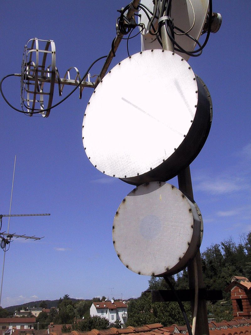
Fig.6.1 - 23cm & 13cm SBFAs used for 1.2Mbps packet-radio access.
(CAVITY)
(HORN)
(CUP)
(SBFA)
(ARCHERY)
(SELECT)
(HOME)
Weatherproof UHF & microwave cavity antennas
Matjaz Vidmar, S53MV
6. Selection of the most suitable antenna
Although the whole family of microwave cavity antennas is very large, many of these antennas are not known to the wider public. Little if any serious articles have been published in the amateur-radio literature. Therefore it was decided to write this article including the description of the most interesting microwave cavity antennas, their past experience, present performance and expected future developments.
Fig.6.1 - 23cm & 13cm SBFAs used for 1.2Mbps packet-radio access.
Unfortunately, most people select an antenna only according to its directivity or gain. WRONG! There are many more selection parameters and all of them need to be considered: width and shape of the main beam, side-lobe levels and directions, frequency bandwidth, sensitivity to environmental conditions and weather effects, ease of manufacturing etc.
Microwave cavity antennas may not provide the maximum number of decibels for a given quantity of aluminum. This may explain why they are not so popular. On the other hand, microwave cavity antennas may be simple to manufacture, insensitive to manufacturing tolerances, have low side-lobe levels, be reasonably broadband, easy to make weatherproof and insensitive to environmental conditions, quickly rejecting rain drops, snow and ice from accumulating on their radiating apertures.
While designing a radio link, the first consideration should be the antenna beam-width according to the desired coverage. Antenna arrays should only be considered in a second place, when a single antenna is unable to provide the desired coverage. The most common mistake is to select the antenna with the largest number of decibels. Its beam may be too narrow, its large side-lobes may pick interference and multipath and its deep nulls in the radiation pattern cause dropouts and pointing problems.
This article includes detailed descriptions of different cavity antennas: simple horn (7dBi & 90 degrees), cup dipole (12dBi & 50 degrees) and SBFA (16dBi & 30 degrees). All these designs are well tested and foolproof: it is just a matter of selecting the right design for a particular application. A SBFA is an excellent replacement and performs better than small (less than 1m diameter) parabolic dishes with poorly designed feeds at relatively low frequencies (below 2GHz).
On the other hand, a successful duplication of the "archery-target" antenna (20.5dBi & 12 degrees) and its likely future developments requires some skill and appropriate test equipment. The intention of this article was to show that there is still development going on in the antenna field, providing some hints to serious antenna experimenters.
References
[1] A. Kumar, H. D. Hristov: "Microwave Cavity Antennas", Artech House, 1989, ISBN 0-89006-334-6.
[2] H. W. Ehrenspeck: "A New Class of Medium-Size, High-Efficiency Reflector Antennas", IEEE Transactions on Antennas and Propagation, March 1974, pp. 329-332.
[3] Matjaz Vidmar: "An Archery-target Antenna", Microwave Journal, May 2005, pp. 222-230.