Fig.3.1.1 - Basic design of a cup dipole.
(CAVITY)
(HORN)
(CUP)
(SBFA)
(ARCHERY)
(SELECT)
(HOME)
Weatherproof UHF & microwave cavity antennas
Matjaz Vidmar, S53MV
3. Cup dipole
3.1. Basic design of a cup dipole
In order to increase the gain of a waveguide horn, the size of the aperture has to be increased without exciting too many higher-order waveguide modes. A rather simple solution is to make a smooth transition from the waveguide to the larger aperture in the form of a pyramidal or conical horn. Such a solution becomes unpractical at lower microwave frequencies and UHF, where the size of the horn is too large.
An alternative solution is to avoid exciting unwanted modes already at the transition from an arbitrary TEM feed line to the waveguide. Replacing a simple feed probe with a symmetrical half-wave dipole avoids exciting the unwanted TM01 mode while exciting the desired TE11 mode. Such a solution is called a cup dipole and is represented on the following drawing:
Fig.3.1.1 - Basic design of a cup dipole.
A cup dipole is a really compact antenna with a directivity of up to 12dBi and a very clean radiation pattern with very weak side-lobes. The directivity achieves its maximum at the second peak on the Ehrenspeck 's diagram [2]. Again, most of the metallic antenna structure can be used as a radome at the same time and just the radiating aperture needs to be covered with a transparent cover.
A cup dipole provides a -3dB beam width of about 50 degrees. Besides operating as a stand-alone antenna, a cup dipole also makes an excellent feed for a shallow (f/d=0.6-0.7) parabolic dish.
3.2. Cup dipole for 23cm
The construction of a practical cup dipole for 23cm (13cm) is shown on the following drawing:
Fig.3.2.1 - Practical cup dipole for 23cm (13cm).
If only simple tools are available, then it makes sense to build the individual components of the cup dipole from aluminum sheet and bolt them together with small M3X4 or M3X5 screws. Aluminum is a good electrical conductor providing low losses in the antenna structure and does not require any special environmental protection. The required mechanical components for the cup dipole for 23cm are shown on the following drawing:
Fig.3.2.2 - Mechanical components of the cup dipole for 23cm.
The front cover may be quite thick FR4 laminate or plexi-glass, since a dielectric plate in this position actually improves the performance of a cup dipole.
The measured E-plane and H-plane radiation patterns of the prototype cup dipole are shown on the following plots:
Fig.3.2.3 - E-plane and H-plane radiation patterns of the cup dipole for 23cm.
The measured patterns in both planes at a number of different frequencies were used to compute the directivity as shown on the following plot:
Fig.3.2.4 - Directivity of the cup dipole for 23cm.
The kink in the directivity curve will be explained later together with the same effect observed with the prototype for 13cm.
3.3. Cup dipole for 13cm
The design of the cup dipole can be easily scaled to the 13cm band. The required mechanical components for the cup dipole for 13cm are shown on the following drawing:
Fig.3.3.1 - Mechanical components of the cup dipole for 13cm.
The antenna is first assembled together using just bolts, making all necessary adjustments and checkouts. Afterwards the antenna is disassembled so that all seams can be sealed with small amounts of silicone sealant. Finally, do not forget a venting hole or unsealed seam in the bottom part of the antenna, where any (condensation) moisture can find its way out of the antenna!
A homemade cup dipole for 13cm that already provided several years of outdoor service is shown on the following picture:
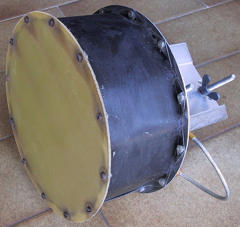
Fig.3.3.2 - Cup dipole for 13cm.
The measured E-plane and H-plane radiation patterns of the prototype cup dipole for 13cm are shown on the following plots:
Fig.3.3.3 - E-plane and H-plane radiation patterns of the cup dipole for 13cm.
The measured patterns in both planes at a number of different frequencies were used to compute the directivity as shown on the following plot:
Fig.3.3.4 - Directivity of the cup dipole for 13cm.
As the frequency increases, the directivity plots of both cup dipoles for 23cm and 13cm include a kink. A further explanation of what is happening is given by the following two E-plane radiation patterns for both investigated antennas: the 23cm cup dipole at 1370MHz and the 13cm cup dipole at 2480MHz:
Fig.3.3.5 - Corruption of the radiation patterns of cup dipoles at high frequencies.
Both radiation patterns are badly corrupted due to the appearance of higher-order symmetrical waveguide modes. These are excited by a perfectly symmetrical half-wave dipole and are no longer suppressed by the waveguide. The size and directivity of a cup dipole therefore has a practical upper limit.
Beyond this limit different solutions are required to control the illumination of the aperture to obtain even narrower radiation beams and higher values of directivity.
3.4. Cup dipole for 70cm
The opposite happens at UHF and lower frequencies: all presented cavity antennas are physically too large to be practical. At low frequencies, a good hint is to look at the design of very compact coaxial-to-waveguide transitions. A practical solution in the 70cm band is a downscaled cup dipole as shown on the following drawing:
Fig.3.4.1 - Practical (downscaled) cup dipole for 70cm.
The aperture of this downscaled cup dipole corresponds to a simple waveguide horn. The expected radiation pattern is therefore similar to the much longer waveguide horn and the expected directivity is 8dBi or less. 8dBi may not seem much, but remember that this figure is achieved with a compact and weatherproof antenna at a relatively low frequency!
Since the half-wave dipole is installed rather close to the cavity wall, its expected radiating impedance will be very low. A folded dipole is therefore used for impedance transformation. The folded dipole is built on a printed-circuit board and requires a balanced 50-ohm feed.
The balun is simply a quarter-wavelength piece of RG-316/U thin teflon-dielectric coaxial cable forming a two-turn coil. The dipole is built on a piece of 1.6mm-thick FR4 laminate with 35um or thicker copper cladding. No etching is usually required. The copper cladding is marked with a sharp tip and the unnecessary copper foil is simply peeled off.
All of the folded-dipole components are shown on the following drawing, including two aluminum brackets used to bolt the dipole to the cavity wall:
Fig.3.4.2 - Folded-dipole dipole components for 70cm.
The measured E-plane and H-plane radiation patterns of the prototype cup dipole for 70cm are shown on the following plots:
Fig.3.4.3 - E-plane and H-plane radiation patterns.
The measured patterns in both planes at a number of different frequencies were used to compute the directivity as shown on the following plot:
Fig.3.4.4 - Directivity of the cup dipole for 70cm.