Fig.4.1.1 - Design of a short-backfire antenna (SBFA).
(CAVITY)
(HORN)
(CUP)
(SBFA)
(ARCHERY)
(SELECT)
(HOME)
Weatherproof UHF & microwave cavity antennas
Matjaz Vidmar, S53MV
4. Short-backfire antenna (SBFA)
4.1. Design of a short-backfire antenna (SBFA)
As the diameter of the cup-dipole cavity increases beyond 1.4 wavelengths, additional symmetrical circular-waveguide modes are excited by the dipole feed and propagated in the waveguide. These modes spoil the aperture illumination, increase the side-lobe levels and decrease the antenna directivity. In order to build even larger cavity antennas, some means of controlling the amplitude and phase of all contributing modes has to be introduced.
The most popular solution to control the amplitude and phase of symmetrical modes inside a circular waveguide is to introduce an additional circular plate in the aperture plane. This plate is called the small reflector while the cavity is called the large reflector. Together with one or more feed dipoles, these two reflectors form a very efficient cavity antenna called the short-backfire antenna or SBFA:
Fig.4.1.1 - Design of a short-backfire antenna (SBFA).
The large reflector of a SBFA has a diameter D of up to 2.5 wavelengths while the small reflector has a diameter of about one-half wavelength or slightly more. The rim height h is usually around one-half wavelength. The directivity of such a simple antenna exceeds 16dBi with an aperture efficiency close to 100% corresponding to the third peak on the Ehrenspeck 's diagram [2]. Again, most of the metal structure can be used as a radome and just the radiating aperture needs to be covered with a transparent cover.
A SBFA provides a -3dB beam width of about 30 degrees. The whole antenna structure is not critical and is able to operate over bandwidths of more than 10% of the central frequency. Since the SBFA reflector structure is rotationally symmetrical, the polarization only depends on the feed. Two feed dipoles may be used for dual polarization or circular polarization.
4.2. SBFA for 23cm
The construction of a practical SBFA for 23cm (13cm) is shown on the following drawing:
Fig.4.2.1 - Practical SBFA for 23cm (13cm).
The front panel (radome) may act as a support for the small reflector, thus considerably simplifying the mechanical design of the antenna. The radome has some measurable effect on the SBFA and any dielectric should not be too thick. If only simple tools are available, then it makes sense to build the metal components of the SBFA from aluminum sheet and bolt them together with small M3X4 or M3X5 screws.
The front panel (radome) is a disc of 1.6mm (0.8mm for 13cm) FR4 laminate. The small reflector is a disc of copper foil (35um or thicker cladding). No etching is usually required. The copper cladding is marked with a sharp tip and the unnecessary copper foil is simply peeled off. The required mechanical components for the SBFA for 23cm are shown on the following drawing:
Fig.4.2.2 - Mechanical components of the SBFA for 23cm.
The measured E-plane and H-plane radiation patterns of the prototype cup dipole are shown on the following plots:
Fig.4.2.3 - E-plane and H-plane radiation patterns of the SBFA for 23cm.
The measured patterns in both planes at a number of different frequencies were used to compute the directivity as shown on the following plot:
Fig.4.2.4 - Directivity of the SBFA for 23cm.
4.3. SBFA for 13cm
The design of the SBFA can be easily scaled to the 13cm band. Since the SBFA is sensitive to the radome thickness, the latter has to be scaled to the higher frequency as well! The required mechanical components for the SBFA for 13cm including the radome from 0.8mm thick FR4 laminate are shown on the following drawing:
Fig.4.3.1 - Mechanical components of the SBFA for 13cm.
The antenna is first assembled together using just bolts, making all necessary adjustments and checkouts. Afterwards the antenna is disassembled so that all seams can be sealed with small amounts of silicone sealant. Finally, do not forget a venting hole or unsealed seam in the bottom part of the antenna, where any (condensation) moisture can find its way out of the antenna!
A homemade SBFA for 13cm is shown on the following picture:
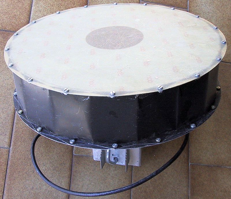
Fig.4.3.2 - Homemade SBFA for 13cm.
The measured E-plane and H-plane radiation patterns of the prototype SBFA for 13cm are shown on the following plots:
Fig.4.3.3 - E-plane and H-plane radiation patterns of the SBFA for 13cm.
The measured patterns in both planes at a number of different frequencies were used to compute the directivity as shown on the following plot:
Fig.4.3.4 - Directivity of the SBFA for 13cm.
As the frequency increases, the H-plane side-lobes of both SBFAs for 23cm and 13cm increase. As the diameter of the antenna D exceeds 2.5 wavelengths, the side-lobes become so large that the directivity of the antenna starts decreasing.
4.4. Feeds for SBFAs and cup dipoles
A half-wave dipole is the simplest way to feed cup-dipole and/or SBFA cavities. Microstrip-patch antennas or rectangular or circular metal waveguides can also be used. A half-wave dipole requires a balun to be fed with standard 50-ohm coaxial cable.
Besides the directivity bandwidth of a cup dipole and/or SBFA, the gain bandwidth of these antennas is also limited by the impedance matching of the feed. In the case of a SBFA, the feed is enclosed between the large and small reflectors, resulting in a low radiation impedance and corresponding sharp resonance. The impedance-matching bandwidth is likely much narrower than the bandwidth of operation of the SBFA cavity.
An impedance mismatch results in a loss of antenna gain. In the case of microwave cavity antennas, this is the only significant loss mechanism, since the electrical efficiency of the cavities themselves is close to unity. A good estimate for the antenna gain is therefore just subtracting the impedance-mismatch loss from the directivity.
The antenna bandwidth can be improved by a broadband feed dipole. One possible solution is to build the feed dipole from semi-rigid coaxial cable and use its internal conductor as a reactive load to broaden the impedance-matching bandwidth. The same type of semi-rigid cable can also be used for the balun including a dummy arm. The wiring of such a dipole and corresponding balun is shown on the following drawing:
Fig.4.4.1 - Dipole & balun wiring diagram.
A practical solution is to build the feed dipoles and corresponding baluns from UT-141 semi-rigid cable (outer diameter about 3.6mm) in the 23cm frequency band and from UT-085 semi-rigid cable (outer diameter about 2.2mm) in the 13cm band as shown on the following drawing:
Fig.4.4.2 - Feeds for 23cm & 13cm cup dipoles and SBFAs.
A suitable coaxial connector for semi-rigid cable should be selected first. N connectors may be useful in the 23cm band. Smaller SMA or TNC connectors may be used in the 13cm band. While soldering semi-rigid coaxial cables one needs to take into account the thermal expansion of their teflon dielectric!
The dipole is made by cutting the specified length "A" of semi-rigid cable. Then "D" millimeters of outer conductor and teflon dielectric are removed at both ends. After this operation the outer-conductor copper tube is carefully cut in the center and both parts are pulled away to form the gap "C". Finally both dipole ends are filled with solder to connect the center and outer conductors.
The published 23cm SBFA with the described feed achieves a return loss better than -10dB over the whole 1240-1300MHz frequency band. The 13cm SBFA design has a slightly higher directivity resulting in a narrower bandwidth. The 13cm SBFA with the described feed achieves a return loss of -10dB over the frequency band 2300-2360MHz.
The cavities of cup dipoles represent a different load for the feed dipoles, therefore the dimensions of the feed dipoles are necessarily different from those used for the SBFAs. The impedance-matching bandwidth of cup dipoles is much broader than SBFAs and a return loss of -15dB can usually be achieved.