Fig.1.2.1 - Ehrenspeck 's directivity plot for round cavities.
(CAVITY)
(HORN)
(CUP)
(SBFA)
(ARCHERY)
(SELECT)
(HOME)
Weatherproof UHF & microwave cavity antennas
Matjaz Vidmar, S53MV
1. Weatherproof antennas for UHF and lower microwave frequencies
1.1. Radio-amateurs, weather effects and antenna design
Quite frequently, radio-amateur antenna design is limited to a few popular antenna types. Directional-antenna designs are usually limited to Yagi antennas for the lower frequencies and parabolic dishes for the microwave frequency bands. The operation of a Yagi antenna is based on a collimating lens made of artificial dielectric like rods, loops, disks or helices. The basic design goal of all these slow-wave structures is to achieve the maximum antenna directivity with the minimum amount of material (metal).
The situation is actually made worse with the availability of inexpensive antenna-simulation tools for home computers. The latter provide designs with fantastic gain figures using little hardware. Unfortunately, these results are barely useful in practice. Besides impedance-matching problems, such designs are extremely sensitive to manufacturing tolerances and environmental conditions: reflections from nearby objects and accumulation of dirt and/or raindrops on the antenna structure.
The operation of a 2m (144MHz) Yagi with thin rods (or loops or helix) antenna will be completely disrupted if snow or ice accumulates on the antenna structure. Raindrops accumulated on the antenna structure will completely compromise the operation of a 23cm (1.3GHz) or 13cm (2.3GHz) Yagi antenna. Manufacturing tolerances limit practical Yagi antennas to frequencies below about 5GHz.
Professional VHF Yagi antennas use very thick rods to limit the effects of snow and ice on the antenna performance. All professional Yagi antennas above 300MHz are completely enclosed inside radomes made of insulating material that is transparent to radio waves. Since any radome includes some dielectric and the latter has a considerable effect on any Yagi antenna, a Yagi antenna has to be completely redesigned for operation inside a weatherproof enclosure. If some natural dielectric (radome) is added, then some artificial dielectric (Yagi rods) has to be removed to maintain the same focal length of the dielectric collimating lens.
Simply speaking, any serious design of a weatherproof Yagi antenna for frequencies above 300MHz is out-of-reach for most amateurs. Fortunately there exist other antenna solutions for amateur-radio equipment that has to operate unattended on mountain tops like FM voice repeaters, ATV repeaters, packet-radio nodes and microwave beacons. The most popular solutions are arrays of dipoles, quads, eights etc. The installation of the latter inside suitable weatherproofing radomes is much less critical than the weatherproofing of Yagis or helices.
1.2. Practical cavity antennas
Of course, a different antenna-design approach may provide much better results, like considering the weatherproofing issue right from the beginning! Cavity antennas may initially require more metal for the same decibels of antenna gain. On the other hand, a cavity antenna is relatively easy to weatherproof: most of the radome is the metal cavity itself and just a relatively small radiating aperture has to be additionally protected with some transparent material.
Before deciding for a particular cavity-antenna design, it makes sense to check well-known solutions. A comprehensive description of many different cavity antennas is given in the book [1]. A useful selection tool is the following directivity plot as a function of cavity diameter as published by Ehrenspeck [2]:
Fig.1.2.1 - Ehrenspeck 's directivity plot for round cavities.
Although Ehrenspeck 's diagram is a little bit optimistic regarding the achievable antenna directivity, it shows many important features of cavity antennas. The plot has local maxima and minima, meaning that not just every cavity size works fine. There are some cavity sizes that provide particularly good antenna performance. These fortunate cavity sizes may achieve aperture efficiencies beyond 100%!
It is interesting to notice that the real directivity plot does not come to an end as suggested by Ehrenspeck many years ago. As shown at the end of this article, the real directivity plot has at least one additional maximum, corresponding to the recently developed "archery-target" antenna [3]. Probably there are many more maxima at larger cavity diameters yet to be investigated.
Another important design parameter is the cavity height or (conductive) rim height surrounding the cavity. The maximum directivity is achieved at rim heights of one half wavelength or slightly above this value, regardless of the particular cavity diameter, as shown on the following plot:
Fig.1.2.2 - Directivity as a function of rim height.
As shown on the above plots, cavity antennas fill an important directivity gap between at least 7dBi and 20dBi. Since cavity antennas are simple to manufacture including weatherproofing, parabolic dishes become practical only if directivities of 22dBi or above are required.
Many practical cavity antenna designs follow directly the above-mentioned directivity plots. The most important are presented in this article including practical weatherproof designs for the amateur-radio frequency bands of 435MHz (70cm), 1.3GHz (23cm) and 2.3GHz (13cm). Some other important designs are omitted due to space limitations, like square cavities and cavities fed with microstrip patches.
All presented antennas were built and accurately tested many years ago at our outdoor antenna test range at the Department for Electrical Engineering of the University of Ljubljana, thanks to Mr. Stanko Gajsek. All directivity values and plots were computed from the measured E-plane and H-plane radiation patterns.
The measured radiation patterns shown in this article are all plotted on a 40dB logarithmic scale to have an excellent view of the sidelobes and any other side effects. Please note that it is relatively easy to hide antenna-design deficiencies by using a linear scale or a 20dB logarithmic scale!
All presented antennas include a transparent radome that is already part of the antenna structure. Therefore little if any additional effort is required for complete weatherproofing of these antenna designs. For terrestrial (horizontal) radio links the radiating surface is vertical, therefore rain drops, snow and ice quickly fall away if they ever stick onto the radome. Finally, the radiating surface is an equi-phase surface, meaning that a uniform coverage with ice or other foreign material does not defocus the antenna.
The presented antennas were initially used for 38.4kbps and 1.2Mbps links in the amateur packet-radio network in Slovenia. Some of these antennas accumulated 15 years of continuous operation in extreme climatic environments on mountaintops. During these 15 years, rain, snow and ice never caused any link dropouts.
A typical example is the packet-radio node CPRST:S55YCP installed on a mountain hut about 1840m above-sea-level and powered by solar panels. The antenna system of the latter includes a GP for 2m, two cup dipoles for 70cm, one cup dipole for 23cm, one SBFA for 23cm, one SBFA for 13cm and a webcam as shown on the following picture:
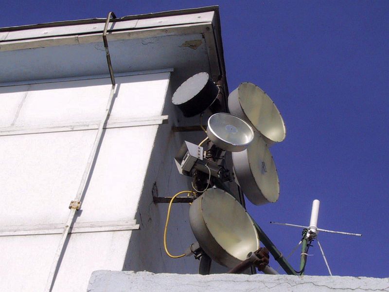
Fig.1.2.3 - Cup dipoles and SBFAs of CPRST:S55YCP.