(SWS)
(CIGAR)
(DESIGN)
(1G3)
(2G4)
(3G4)
(HOME)
Cigar antennas for 1.2GHz, 2.4GHz and 3.4GHz
Matjaz Vidmar, S53MV
3. Design of cigar antennas
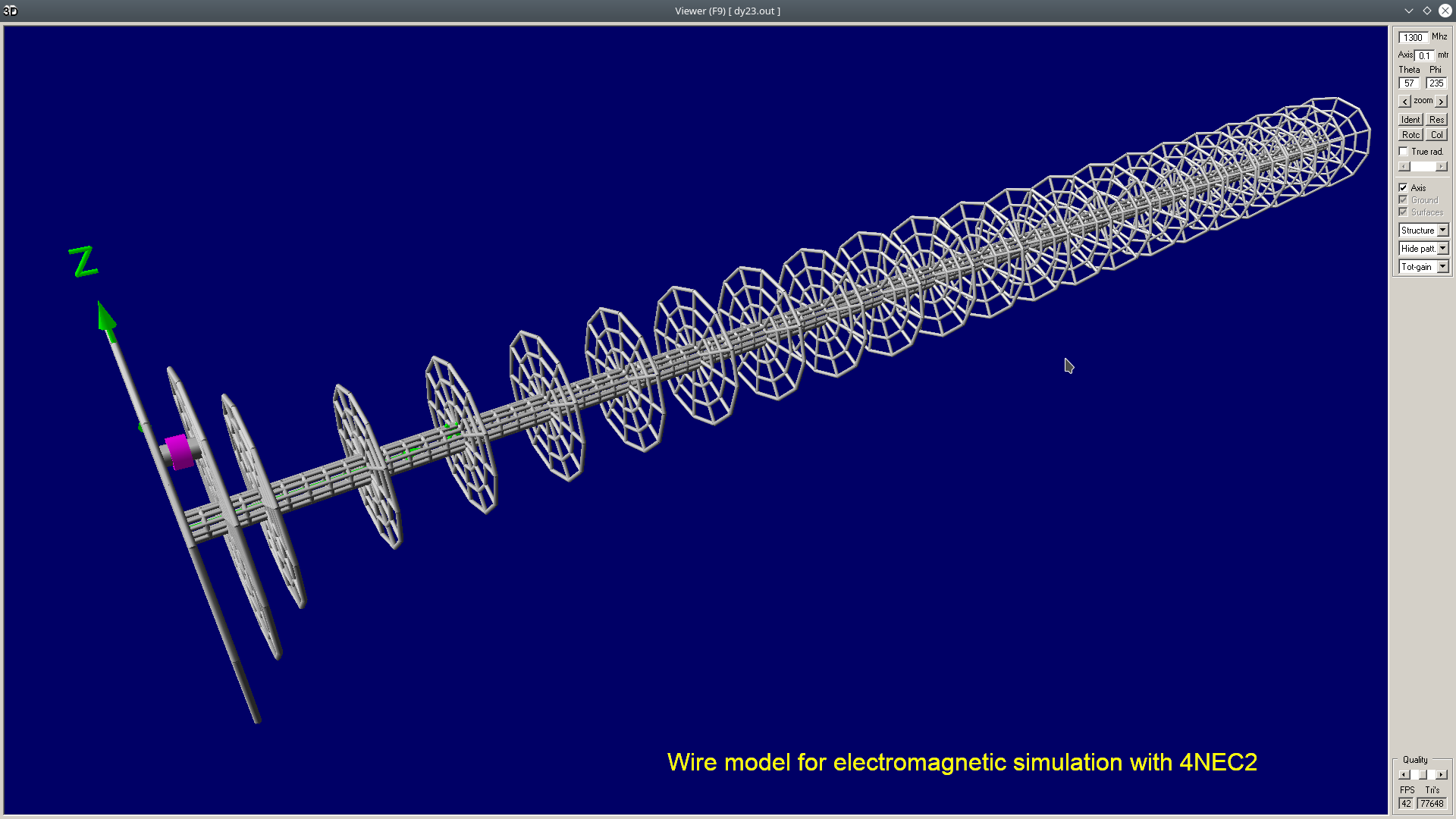
In a cigar antenna, both the disk elements and their metal carrier (boom) have important electromagnetic functions. An electromagnetic simulation of a complex antenna structure may be made from many small wire segments. The simulation of a cigar antenna requires several thousands of small wire segments. For the same degree of accuracy, usually more wire segments are required to simulate the metal boom than the disk elements:
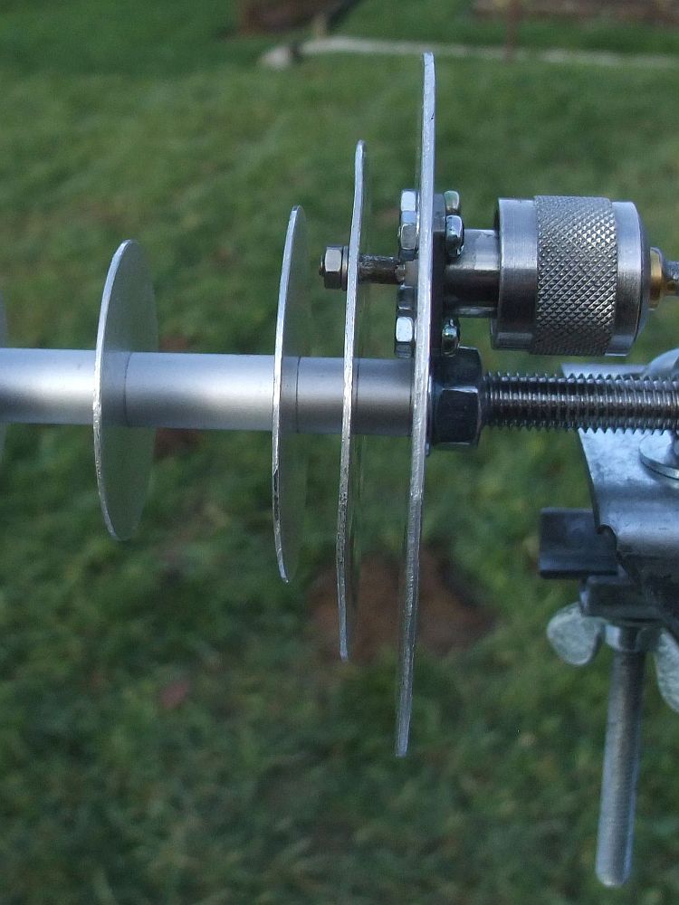
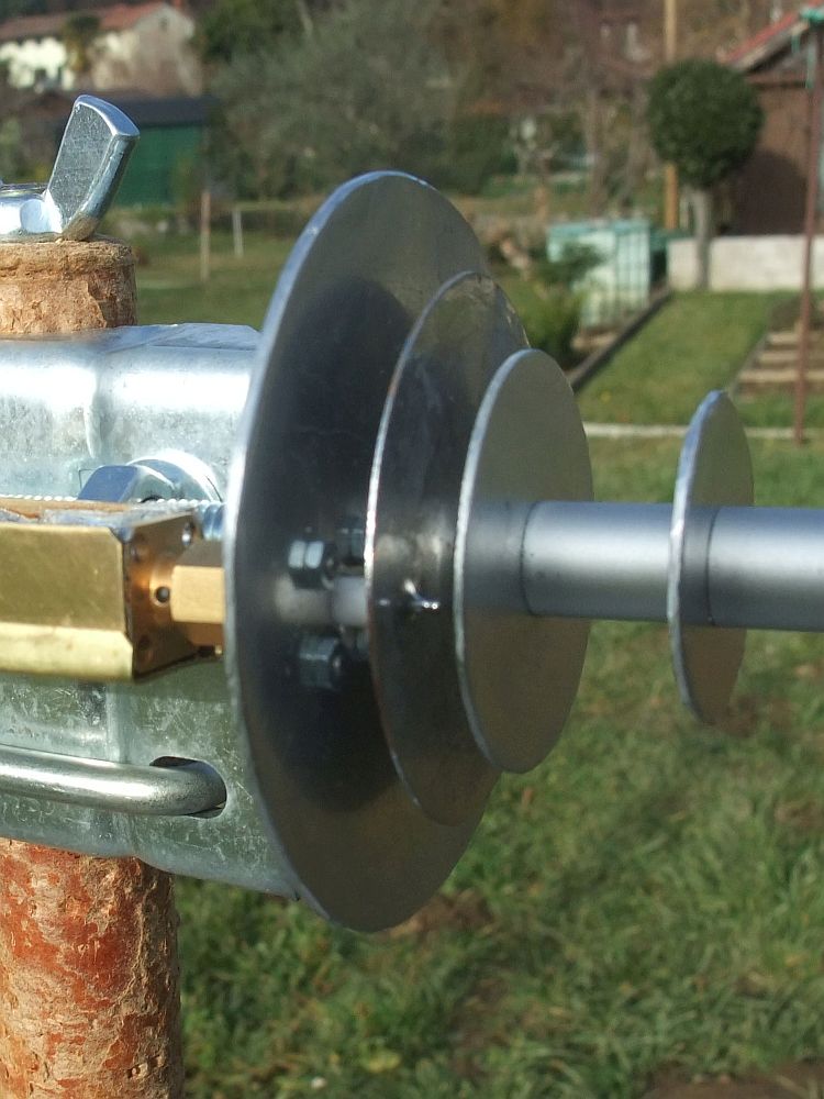
The designs presented in this article use many hints from the famous Russian cigar antenna "BDM-2", described in detail on the web forum https://www.wifi-antennas.com for different frequency ranges, polarizations and element numbers. A threaded rod carries both disks and spacers. The threaded rod is made from stainless steer for mechanical strength. To minimize electrical losses, both disks and spacers should be made from a material with a high electrical conductivity like aluminum (Al). The whole antenna is held together with just two nuts at both ends of the threaded rod. Both nuts should be tightened to ensure a good electric contact among the disks and spacers:

The cigar feed includes a reflector "R", a driven element "S" and the first director "D1". All other directors "D2-N" are of the same size at the same spacings forming a uniform slow-wave structure acting as an artificial-dielectric lens. The "BDM-2" cigar uses closely spaced directors at ~ 0.185λ to obtain both a high directivity and a large bandwidth for a given antenna boom length "l". Please note that the element spacing includes both the spacer "d" and the disk thickness!
The impedance of the antenna is controlled by the driven element "S" diameter and feedpoint eccentricity "e". The driven element "S" diameter selects the frequency. The feedpoint eccentricity "e" selects the magnitude of the impedance. It seems that the orignal "BDM-2" cigar was designed for an impedance match to 75Ω (inexpensive coaxial cable with "F" connectors) or even higher? An impedance match to 50Ω requires a smaller feedpoint eccentricity "e" than published for the "BDM-2" cigar. In any case, computer simulations for large and complex structures like long cigar antennas tend to produce inaccurate results for the feed-point impedance.
The impedance-match bandwidth of the described cigar antenna is usually narrower than the slow-wave-structure bandwidth. The first director "D1" is usually used to broaden the impedance match. Due to the close spacing "p" between the driven element "S" and the first director "D1", the effect of the latter on the antenna radiation pattern and directivity is very small. On the other hand, a small spacing "p" between the driven element "S" and the reflector "R" decreases the impedance-match bandwidth but reduces the unwanted side lobes thus increasing the directivity and gain.
The presented feed generates a single linear polarization. Dual orthogonal linear polarizations can be obtained with two coaxial connectors fitted to the same antenna, spaced at 90° around the antenna axis. Circular polarization can be obtained with an elliptical driven element "S" with the ellipse axes at ±45° from the feedpoint. The orientation of the major axis of the ellipse selects RCHP or LHCP.
Three different versions of the described cigar antenna were simulated, built several samples each and tested. The version for 1.3GHz has 23 elements on a boom length of about 4λ. The version for 2.4GHz has 33 elements on a boom length of about 6λ. The version for 3.4GHz has 58 elements on a boom length of about 10λ. The proposed boom lengths were chosen to match the available threaded rods of 1m length. The mechanical data of all three versions is presented in the following table:

All directors "D1-N"are made from 1mm thick aluminum sheet. All reflectors "R" use thicker 1.5mm aluminum sheet for mechanical strength. The driven elements "S" for 1.3GHz and 2.4GHz are made from 1mm thick aluminum sheet like the directors and are fed with a N connector. The driven element "S" for 3.4GHz is made from 0.5mm thick brass (Ms) sheet to allow soft soldering of a SMA connector to the feed point. The whole brass disk is tinned to avoid a galvanic reaction with aluminum:
The impedance matches and radiation patterns of all prototypes were carefully measured. The impedance matches were measured with a directional coupler with the directivity better than 30dB, connected to a spectrum analyzer with a tracking generator.
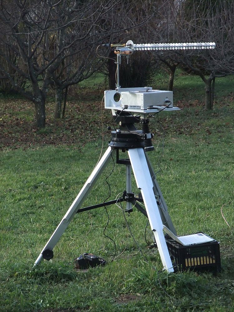
The radiation patterns were measured in an open field approximately 1.5m above ground at a horizontal distance of about 9m. The latter was barely sufficient to fulfill the Rayleigh far-field condition for the 3.4GHz cigar antenna. All other obstacles were kept far away to minimize unwanted reflections.
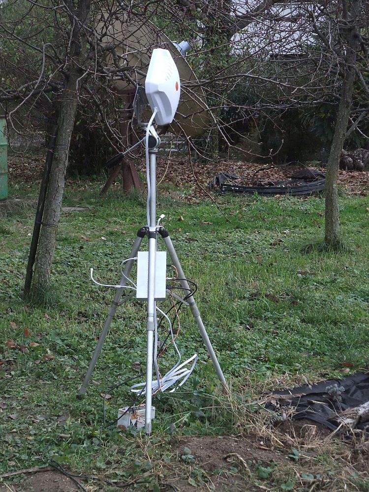
For accurate results, all tested antennas were rotated approximately around their phase center. All tested antennas were on the receiving side of the radio link, equipped with a passband filter and a diode detector installed directly on the antenna. A laptop computer was steering the antenna positioner as well as receiving data from a lock-in receiver:
On the other side of the radio link, a dual-polarized commercial antenna with a directivity of about 10dBi was connected to a +10dBm modulated transmitter. The latter synchronized the lock-in receiver through a long coaxial cable. The lock-in frequency was carefully selected to 10.2kHz to avoid interference form local cellular-phone towers. In the other direction, the transmitter frequency and output power were set through an USB extender cable by the laptop computer on the receiving side.
The radiation patterns of all linearly-polarized prototypes were measured in two planes each: in the electric-field plane E and the magnetic-field plane H. Polarization switching of the transmitter consisted in swapping the two cables of the dual-polarized reference antenna. Polarization switching of the receiving antenna under test consisted in turning the cigar feed by 90°.
The most important design parameter of a slow-wave-structure antenna is its directivity plotted as a function of frequency. The latter was computed from the measured radiation patterns in both E and H planes at a number of different frequencies. Due to the high radiation efficiencies of cigar antennas, the difference between gain and directivity can only be caused by an impedance mismatch.
The optimal frequency of a slow-wave structure decreases as rain, snow and/or ice accumulate on the antenna. Almost all slow-wave-structure antennas are therefore designed for higher than nominal operating frequencies when dry. Thanks to their large bandwidth, cigar antennas are almost insensitive to rain. Cigars are much less sensitive to snow and/or ice as antennas with wire slow-wave structures like rods, crosses, loops or helices. Therefore cigars seldom require radomes!