(SWS)
(CIGAR)
(DESIGN)
(1G3)
(2G4)
(3G4)
(HOME)
Cigar antennas for 1.2GHz, 2.4GHz and 3.4GHz
Matjaz Vidmar, S53MV
6. 58-element cigar antenna for 3.4GHz
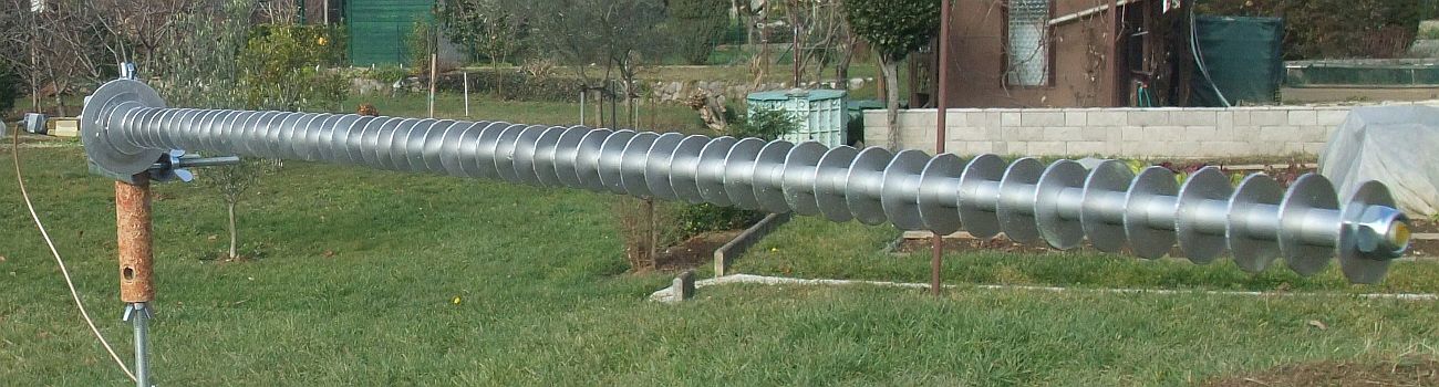
The last experiment was to obtain the highest directivity from an uniform slow-wave structure on an 1m-long M8 threaded rod at 3.4GHz:
Since cutting many disks from aluminum sheet using scissors is very labor-intensive, readily available M8 zinc-plated washers were tried first. The latter had a thickness of 1.3mm and nominal diameter of 30mm. The diameter of available washers measured 29.5mm. Computer simulation without the boom calculated the center frequency around 3.0GHz. Using 15mm long spacers from 10mm/8mm aluminum tube, slow-wave structures of 40 and 50 washers were built and measured. Their center frequency was about 3.3GHz. Due to the zinc-plated steel washers, the resulting antenna was too heavy: the M8 threaded rod bent under the weight of the washers.
Next 55 washers were cut from 1mm aluminum sheet using handheld sheet-metal scissors. Due to inaccurate hand cutting, the aluminum disks achieved a mean diameter of just 27.5mm with unacceptable tolerances up to ±0.5mm. The resulting 58-element cigar antenna (in the above picture) achieved a record measured directivity of 19.6dBi at 3.65GHz (~11λ).
Finally an additional, specialized tool was was made that allowed cutting disks with a small circular saw. First, 8mm diameter holes were drilled in the aluminum sheet. Next, the sheet was roughly hand cut using scissors. Finally, 55 disks of 28.5mm diameter were cut with the specialized tool and circular saw. The resulting 58-element cigar antenna achieved a measured directivity of 19.2dBi at 3.45GHz (~10λ).
Since available N connectors are too large, a flange-mount SMA connector had to be used. The flange was attached to the reflector disk "R" with four screws M2.5x5mm. The center pin was soft-soldered into a 1.5mm-diameter hole in the driven element "S" made from 0.5mm tin-plated brass sheet.
Radiation patterns were first made using a dual-polarized commercial antenna with a directivity of about 10dBi as reference. To further suppress reflections of the antenna test range, another cigar for 3.4GHz was used as reference for the final measurements. Since radiation-pattern measurements were performed in an open field, out-of-band interference from high-power cellular-phone towers had to be suppressed by a microstrip bandpass filter 2200MHz-4000MHz in front of the diode detector. Radiation-pattern artifacts caused by interference were further suppressed by a careful choice of the lock-in frequency. For accurate results, the diode-detector response was calibrated by a precision step attenuator.
The measured radiation patterns of the final version of the 58-element cigar antenna for 3.4GHz (including unwanted reflections of the antenna test range!) are presented in the following gif animations (scanning all frequencies and both polarization planes) in both linear (field) and logarithmic (dB) scales:
The directivity was calculated from both radiation patterns in the E and H planes measured at each particular frequency in the 3000MHz-3800MHz range. At each frequency two different algorithms were used for the directivity: average of inverse partial directivities <Dj> and geometrical average of partial directivities <logDj>. The first is mathematically correct for a large number of cuts (measurement planes) of the radiation pattern while the second provides better results with just two cuts (E and H planes) for fan-beam antennas. Since cigar antennas produce rotationally-symmetrical pencil beams, both algorithms provide similar results:
The impedance matching of the longest version for 3.4GHz was acceptable. The return loss was around -15dB at the desired center frequency. The feed eccentricity "e" had to be reduced from the 18mm initial value down to 16mm to slightly improve impedance matching to 50Ω. The suggested driven-element "S" diameter of 49mm provided the best impedance matching around 3500MHz.
Comparison tests confirmed that thanks to the excellent radiation efficiency and good impedance matching, the gain of the 58-element cigar antenna for 3.4GHz is practically identical to its directivity. Few direct comparisons with commercial antennas for the same gain range could be made, since the latter are usually built as flat-panel arrays with a narrow bandwidth and a poor radiation efficiency η < 50% due to lossy microstrip feed networks.