
(DESIGN)
(COSTAS)
(FRONTEND)
(SUPPLY)
(PCB)
(SHIELD)
(ASSEMBLY)
(TEST)
(HOME)
10Mbps BPSK ZIF transceivers for 1.2GHz, 2.3GHz and 3.4GHz
Matjaz Vidmar, S53MV
2. Costas demodulator
The quadrature outputs I, /I, Q and /Q of the AD8347 Zero-IF receiver carry all of the information in the processed bandwidth while the actual modulation depends on the following demodulator. A practical demodulator for BPSK is the Costas loop. A Costas loop for a Zero IF can be practically implemented with a rotating switch, an EXOR gate and an up/down binary counter. The four most significant bits of the up/down counter control the 16-position switch:
A resistor network is used to transform the 4-phase I, /I, Q and /Q signals into 16-phase signals. A rotary switch is used to select the best phase. Two switches offset by 90 degrees provide the I* and Q* signals corrected for the receiver phase and/or frequency error. The I* signal already represents the output data. The product of I* and Q* represents the error signal to lock the Costas loop. In the digital world, signal multiplication is obtained with an EXOR gate. The VCO of a first-order loop is simply an up/down binary counter.
The described Zero-IF Costas loop with a first-order DPLL modulo 256 (8-bit counter) has been used extensively in BPSK AX.25 packet-radio links operating at 1.2Mbps since 1996. Different Costas demodulators were designed with discrete 74HCxxx logic devices and successfully used in many AX.25 and NBP links. Due to the discrete 74HCxxx logic devices, the counter clock was limited to about 15MHz and the resulting data rate was limited to about 2Mbps.
NBPv2 operating at 10Mbps requires a counter clock frequency in the 100MHz range. A similar circuit with a DPLL modulo 1024 (10-bit counter) "BPSKX" is programmed with the Altera "MAX+plus II 10.2 BASELINE" software in a single fast CPLD chip EPM3032ATC44:
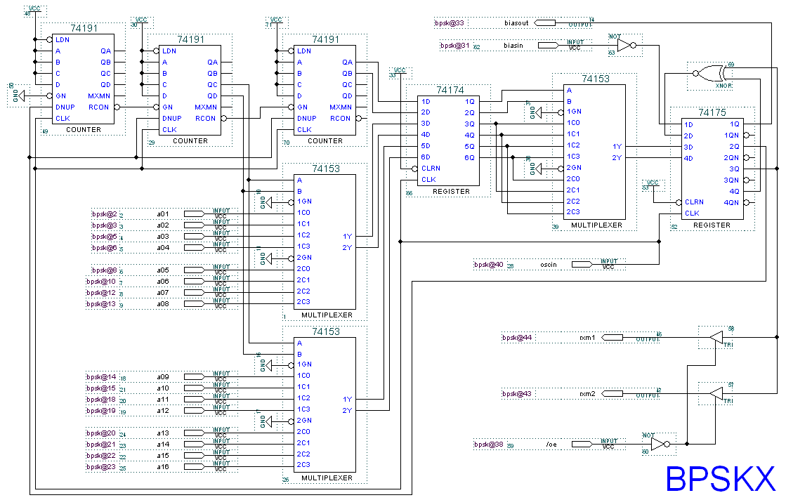
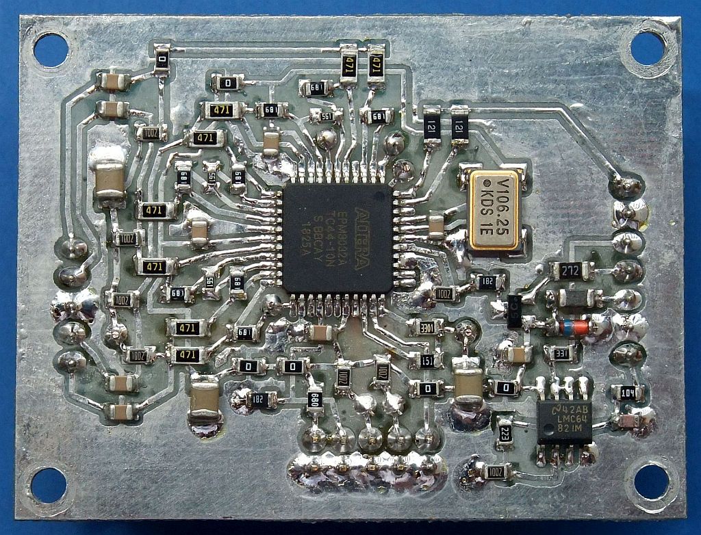
The EPM3032ATC44 CPLD allows analog signals at its digital inputs provided that the bias is selected carefully. The circuit inside the EPM3032ATC44 therefore includes a suitable bias generator. A better solution could be a CPLD or FPGA with differential inputs. The external circuit of the demodulator includes the 16-phase resistor network and clock oscillator:

The demodulator module includes a buffer amplifier for the AGC voltage to provide the RSSI signal. Further the digital-data output RXM (to the TNC clock recovery & descrambler) is suppressed (high-impedance state) during transmission to avoid noisy crosstalk. Some resistors (120ohm, 470ohm and 2.7kohm) are intentionally larger (SMD size 1206) to act as jumpers. The CPLD EPM3032ATC44 is programmed on board through the JTAG connector.
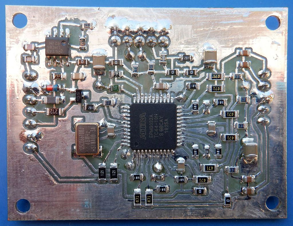
The 10Mbps version includes a 106.25MHz oscillator allowing a carrier-frequency error of about +/-100kHz:
The 2Mbps version includes larger coupling capacitors and a 48MHz oscillator allowing a carrier-frequency error of about +/-40kHz:
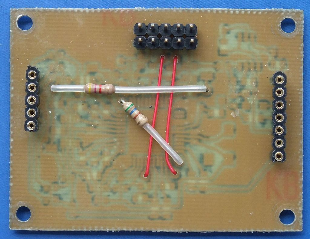
The described Costas-loop demodulator is built on a single-sided printed-circuit board. Just the connectors, two resistors and two wire jumpers are located on the top side of the board:
The described Costas-loop demodulator requires a single supply voltage of 3.3V. The current drain is rather large due to many input CMOS buffers operating in their linear region. It also depends on the input I, /I, Q and /Q signals amplitude. With noise present on the receiver input, the current drain of the 10Mbps version is around 75mA while the current drain of the 2Mbps version is around 65mA.
(DESIGN) (COSTAS) (FRONTEND) (SUPPLY) (PCB) (SHIELD) (ASSEMBLY) (TEST) (HOME)