
(DESIGN)
(COSTAS)
(FRONTEND)
(SUPPLY)
(PCB)
(SHIELD)
(ASSEMBLY)
(TEST)
(HOME)
10Mbps BPSK ZIF transceivers for 1.2GHz, 2.3GHz and 3.4GHz
Matjaz Vidmar, S53MV
7. Assembly of the BPSK transceiver
The different modules of the BPSK transceiver require an external case to provide additional shielding and proper heat dissipation. The simplest solution is a two-piece case from two U-shaped pieces of aluminum sheet. Aluminum sheet does not require painting and allows a good electrical contact between the two U-shaped pieces to improve electromagnetic shielding.
All five modules and three connectors are installed on the bottom "U" made of 1mm-thick aluminum sheet. The piece of aluminum sheet is first cut to size, then drilled according to the plan and finally bent into its final U-shape along the marked lines. Both 1.25GHz and 2.36GHz versions share the same size modules and the same drilling plan:
All internal supply and low-frequency wiring goes through connectors with a 2.54mm pitch. The females are just high-quality IC-socket type strips, the males are corresponding pins. Both need to be gold plated due to the large supply currents. Special care is needed to avoid damaging the female connectors with males of a too large diameter. A damaged female with a too-thick male must be replaced immediately to avoid intermittent contacts.
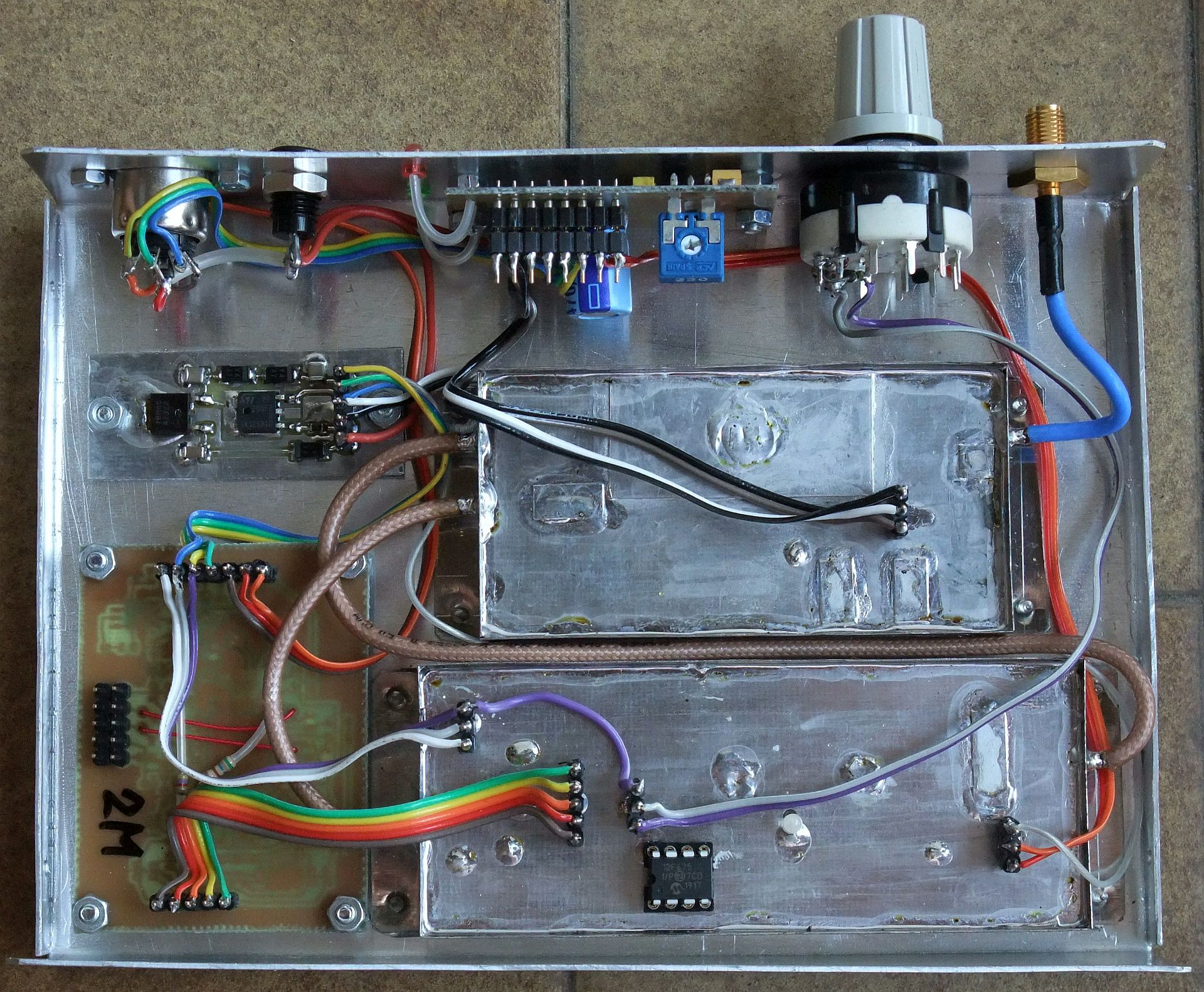
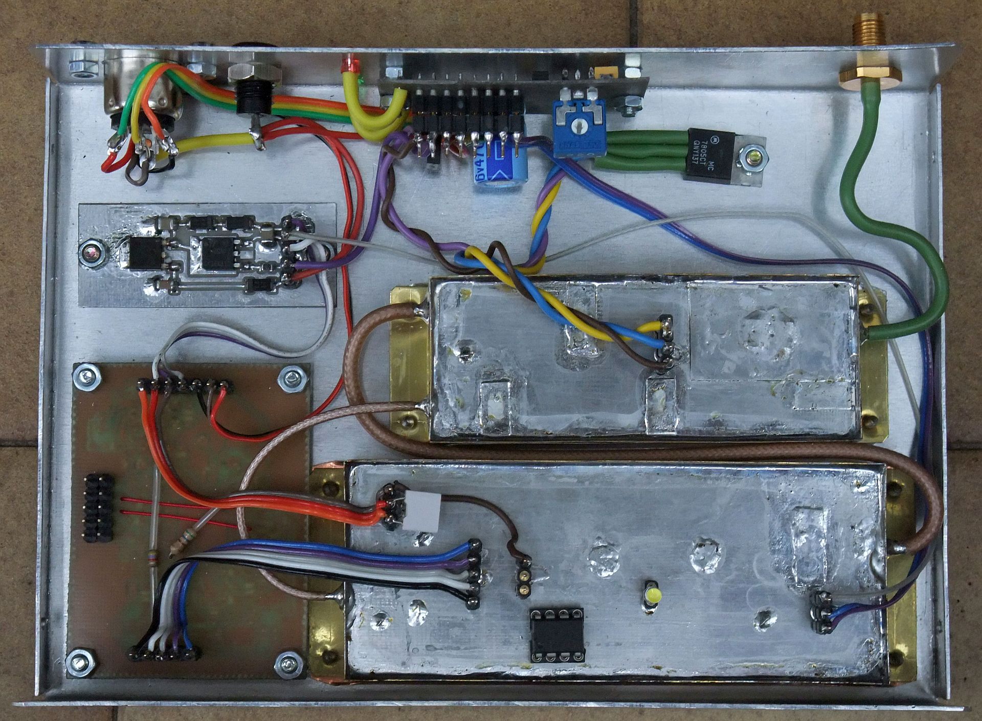
The internal wiring of the 1.25GHz version for 2Mbps, linear supply regulator and module shielding with tinned iron sheet is shown on the following photo:
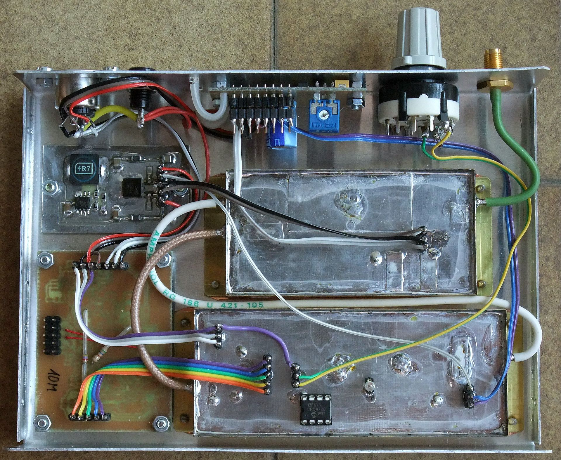
The internal wiring of the 1.25GHz version for 10Mbps and switching supply regulator is shown on the following photo:
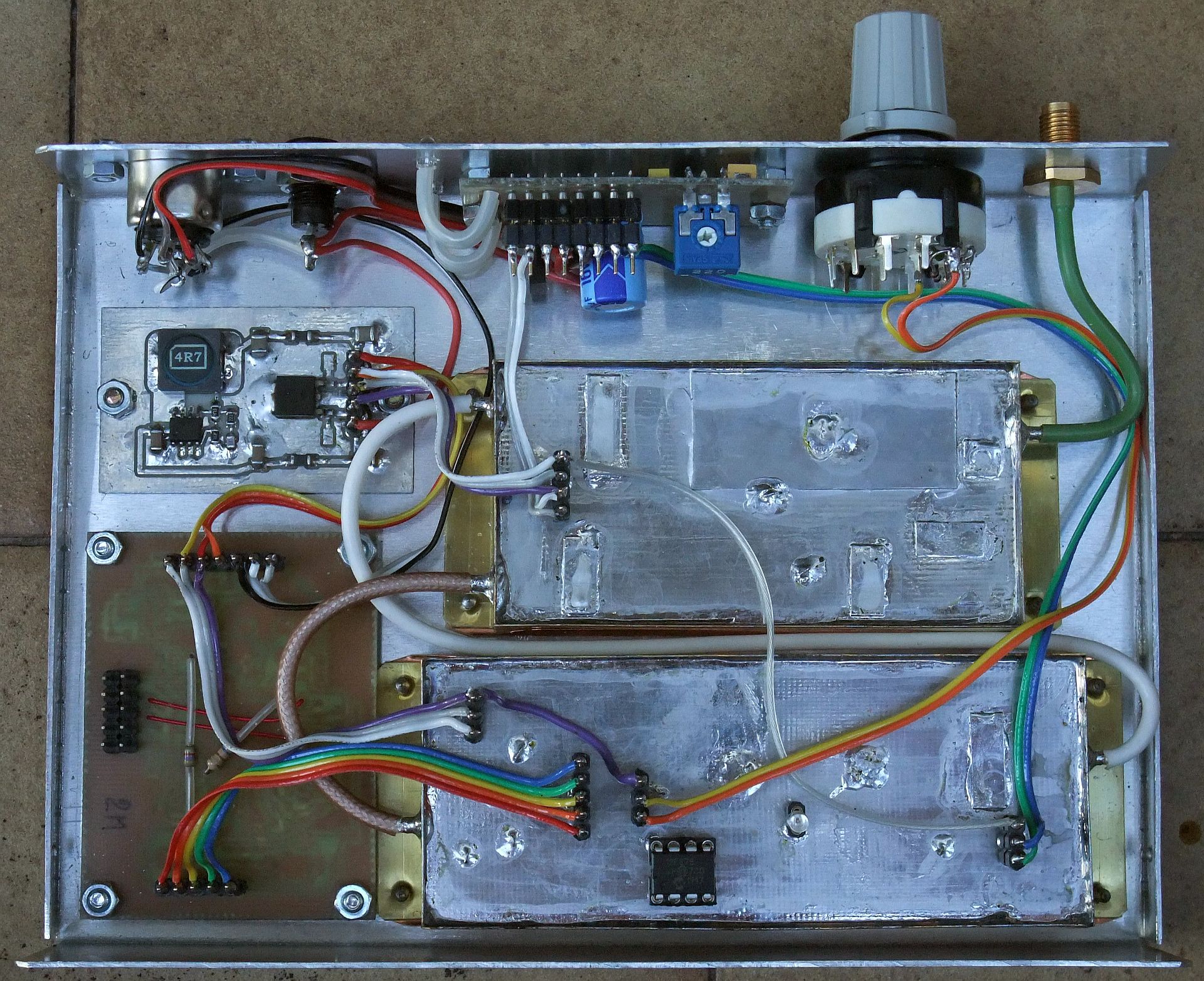
The internal wiring of the 2.36GHz version for 2Mbps and switching supply regulator is shown on the following photo:
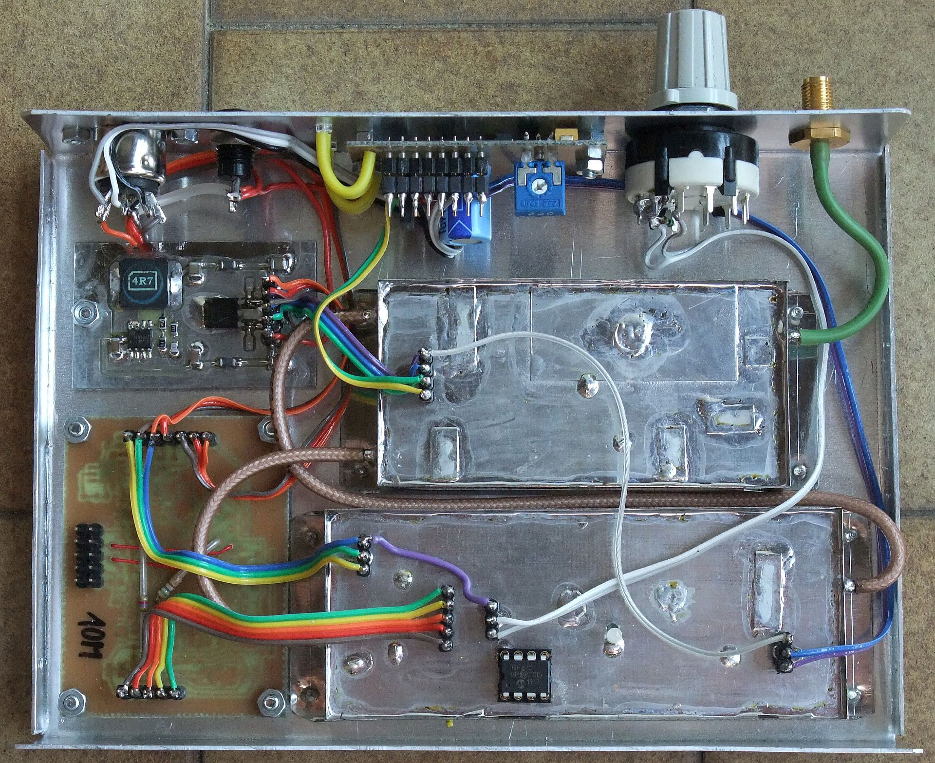
The internal wiring of the 2.36GHz version for 10Mbps, switching supply regulator and module shielding with tinned iron sheet is shown on the following photo:
The 3.41GHz version includes a smaller RF front end and requires an additional 7805 regulator for +5VTX. The drilling plan of the bottom "U" is modified accordingly:

There are two +5VTX supply lines in the 3.14GHz version. The linear supply regulator with the 78M05 and STD20NF20 only supplied the BPSK demodulator with about 165mA. The additional 7805 regulator is required for the RF front end. This additional regulator reduces +12VTX down to +5VTX. Due to the 1.4A current drain of the RF front end, this regulator may dissipate more than 10W. To speed up the RX/TX switching, this 7805 has no additional capacitors at the input nor output.
The 3.41GHz version includes an additional 6.8nF capacitor to stabilize the operation of the AGC. This additional capacitor is soldered on the connector carrying the AGC signal to the RSSI amplifier:
All three versions of the BPSK transceiver for 1.25GHz, 2.36GHz and 3.41GHz have the same cover made form 0.6mm-thick aluminum sheet. The piece of aluminum sheet is first cut to size, then drilled according to the plan and finally bent into its final U-shape along the marked lines. The cover is finally attached to the bottom with four 2.2X6.5mm self-tapping screws:

The external appearance of the three different versions is shown on the following photo. Note that the 3.41GHz version does not have a channel-select switch since there is just a single useful channel at 3.405MHz in the 3400-3410MHz amateur allocation:
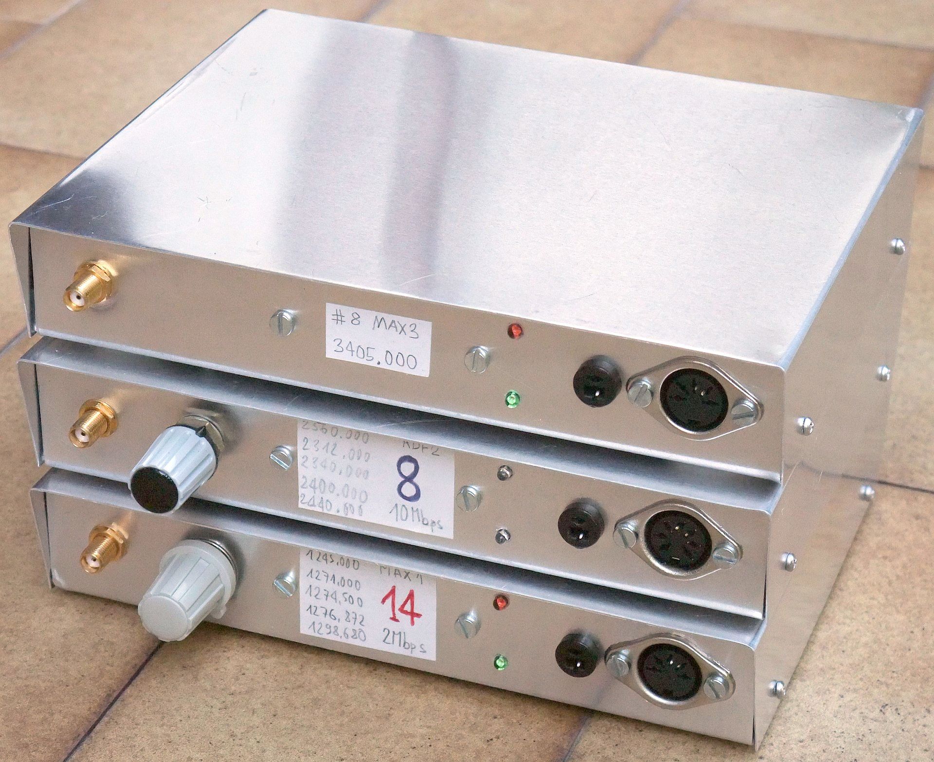
In addition each BPSK transceiver has three connectors and two LEDs on the front panel. The antenna connector is a SMA female for cable installation. Standard DIN connectors are used for the supply and modem signals: "loudspeaker" for the 12VDC supply and 5-pole/180-degree "audio" for the modem signals. The latter include the digital data in both directions RXM and TXM at TTL signal levels, the open collector /PTT switch for 12V and the analog RSSI voltage 0...3.3V:

The RXM, TXM and /PTT signals are required for operation with any TNC. The NBP firmware of the ATNC/AATNC/EATNC (2Mbps) and RATNC/SATNC (10Mbps) further supports RSSI telemetry.
(DESIGN) (COSTAS) (FRONTEND) (SUPPLY) (PCB) (SHIELD) (ASSEMBLY) (TEST) (HOME)