
(HISTORY)
(COUNTER)
(FRONTENDS)
(PROBES)
(ASSEMBLY)
(OPERATION)
(HOME)
Simple RF/Microwave Frequency Counter
Matjaz Vidmar, S53MV
4. Probes
A very common problem of many frequency counters is that these are supplied to the end user without (any) suitable probes! In fact, most RF/microwave sources can not be connected directly to a counter input. The conventional oscilloscope probe is not a good solution for most RF/microwave measurements either. Worst of all, most counters are not even designed to be used with some useful probe types.
Any serious RF/microwave engineer has his/her own set of suitable attenuators, circulators, loads and directional couplers to connect spectrum analyzers, power meters, counters and other instruments to the circuit under test. A complete set of transitions between different RF connectors is also required. Finally, a number of pigtailed connectors to be soldered directly to the circuit under test is always of great help.
A very useful probe to be used with RF/microwave counters is a simple inductive pickup or in other words a 5mm diameter loop at the end of a short length of 50ohm coaxial cable. According to my own experience it does not make sense to make this loop much smaller or larger than 5mm. The same loop can be used from a few MHz up to several GHz. A small resistor (around 50ohm) can be installed in series with the loop to suppress any cable resonances.
The loop is simply approached to inductors or resonators in the circuit under test. The undesired loading of the circuit can be minimized by keeping the loop at the maximum distance that still provides a stable reading on the counter. Finally, the loop probe is never affected by low frequency (50Hz mains or similar) interference. Since the coupling to the circuit under test is not very efficient, it is rather unlikely to damage the counter with large RF signal levels.
A standard oscilloscope probe is a practical solution to measure low frequencies, pulsed signals and in some cases even RF signals.
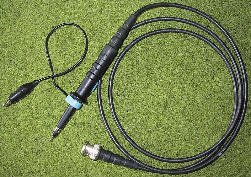
In order to use an oscilloscope probe efficiently, the internal operation of the probe has to be understood. Most probes are equipped with a X1/X10 switch. Further there is a series damping resistor (around 500ohm) to avoid cable resonances that could both corrupt the oscilloscope display and severely disturb the circuit under test.
Finally, one should understand that although the TTL input of the counter operates in excess of 100MHz, the oscilloscope probe may reduce the upper frequency limit to 50MHz or even less!
* * * * *